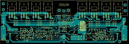
Hi. This is my pcb version of QUASI amp with short protection.
http://www.prikachi.com/images/151/3365151v.jpg
http://www.prikachi.com/images/160/3365160b.jpg
http://www.prikachi.com/images/162/3365162S.jpg
Thanks Apex
Hi
This protection with the values of components for power supply Us = + /-70Vdc!😉
Please give the values of components of protection for the power supply Us = + /-45Vdc?🙄
Thanks
P.S.
Please give a equations to calculate the resistor value of this protection?
Last edited:
This is schematic for +/-45V and 2x2N3055Hi
This protection with the values of components for power supply Us = + /-70Vdc!😉
Please give the values of components of protection for the power supply Us = + /-45Vdc?🙄
Thanks
P.S.
Please give a equations to calculate the resistor value of this protection?
http://bgaudioclub.org/gallery/albums/userpics/11837/shema_gotov_amp.PNG
This is schematic for +/-45V and 2x2N3055
QUOTE]
Vceo for 2N3055 is only 60V??
Brian.
This is schematic for +/-45V and 2x2N3055
QUOTE]
Vceo for 2N3055 is only 60V??
Brian.
For Us = +/-45Vcd with this amplifier to be used 2N3773 (Vceo = 120V),
a power supply Us = + /-70Vcd to use MJ15003 (Vceo = 160V)!!😉🙂
Cheers
Last edited:
which apex550w pcb layout is better?
Give Top layout for PCB the first figure!😕
Thanks!
G-ne Mile!Use this simple DC protect with triac.
In a few words to explain the functions give this DC-protection?😕
Since when Triac MAC224 up and running real short-circuit to ground?!🙁
thanks
Hi all!
For Us = +/-45Vcd with this amplifier to be used 2N3773 or MJ15003 (Vceo=120V or Vceo=140V),
a power supply Us = + /-70Vcd to use MJ15022 or MJ15024 (Vceo=300V or Vceo=350V) !!
Cheers !!
For Us = +/-45Vcd with this amplifier to be used 2N3773 or MJ15003 (Vceo=120V or Vceo=140V),
a power supply Us = + /-70Vcd to use MJ15022 or MJ15024 (Vceo=300V or Vceo=350V) !!
Cheers !!
Last edited:
Hi Mile (Apex)!
I made this your amplifier, with power supply Ucc= + /-68Vcd (2x50Vac), and with the output transistors 8xMJ15003!
When i let the amplifier somewhere with 50% power, after 2 ... 3 hours of work output transistors burn!?
With the diodes D3 and D4 impossible to regulate the bias.
So I made some changes with the transistor - see schematic (Figure 1)
Question: Is this a good solution to the transistor, if not please suggest some other more secure!
thanks and cheers !
P.S.
Zdravo Mile!
Posto slabo mi ide engleski (vidis i sam), dali moze da se obratim na srpski na tvoj E-mail?
Pozdrav
Attachments
You need separate emitter resistors for each output transistor.
They should be a higher value, but can probably be lower power. Maybe 1 ohm, 2 watts each.
They should be a higher value, but can probably be lower power. Maybe 1 ohm, 2 watts each.
Attachments
Last edited:
HiYou need separate emitter resistors for each output transistor.
They should be a higher value, but can probably be lower power. Maybe 1 ohm, 2 watts each.
Is a good bias schematic with BD139 ?! 😕🙄
Regards !
You need separate emitter resistors for each output transistor.
They should be a higher value, but can probably be lower power. Maybe 1 ohm, 2 watts each.
Hi
If you are able to draw a schematic with complementary output pair 2SC5200/2SA1943.
Is good value for C8 = 470nF??!
thanks and cheers !

Last edited:
What you search it's right here.....
Hi radio ,
I have search for you an better schematic , also tested one . I have done small changes for 2SC 5200 as finals .....🙂 I hope you like it .
Regards Alex.
Hi radio ,
I have search for you an better schematic , also tested one . I have done small changes for 2SC 5200 as finals .....🙂 I hope you like it .
Regards Alex.
Attachments
?
Alex, about the protection circuit if i did not put any components on that, will it work properly?
Hi radio ,
I have search for you an better schematic , also tested one . I have done small changes for 2SC 5200 as finals .....🙂 I hope you like it .
Regards Alex.
Alex, about the protection circuit if i did not put any components on that, will it work properly?
Hi radio ,
I have search for you an better schematic , also tested one . I have done small changes for 2SC 5200 as finals .....🙂 I hope you like it .
Regards Alex.
Hi Alex mm (POP) !

Thanks Alex mm well done!
Only if you will give even more protection schematic. For T8 can eat BD139, or need some small changes ?
Last edited:
Minor edits!
Alex mm, whether this schematic is to be processed and output to be a complementary pair with transistors MJ15003/MJ15004?
thanks and cheers !!
Alex mm, whether this schematic is to be processed and output to be a complementary pair with transistors MJ15003/MJ15004?
thanks and cheers !!
- Home
- Amplifiers
- Solid State
- QUASI Amplifier for Beginners