transitor nos
Hi geraldfryjr
hello what transistors you use forECG188 ECG189 trying to make your amp
warm regards
sameer x1
Hi geraldfryjr
hello what transistors you use forECG188 ECG189 trying to make your amp
warm regards
sameer x1
whoa!!!😱...this amp really is powerfull for begginers!!!...😀
hello sir, you say that this diagram was a powerfull amp... so you mean all the spare parts are on the market here in Philippines?
agra guy
yes i am from agra
warm regards
andrew lebon
your nvmos amp pcb is working in 2 ohms 90 volt dc using IRF460 I WILL post pics of rail swinger
yes i am from agra
warm regards
andrew lebon
your nvmos amp pcb is working in 2 ohms 90 volt dc using IRF460 I WILL post pics of rail swinger
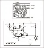
PCB size 25x28mm
very nice sir,
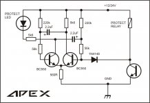
in the schematic there are three transistors but in the pcb two transistors why is that?
Last edited:
very nice sir,
in the schematic there are three transistors but in the pcb two transistors why is that?
Transistor and relay is parts of some protect circuit not parts of 'protect led blinker'.
ok sorry sir.
if u dont mind , ur new protection board and led blink board, how to connect these boards.
if u can pls share protect pcb, fan control pcb, led blinking pcb in pdf format.
thanks.
if u dont mind , ur new protection board and led blink board, how to connect these boards.
if u can pls share protect pcb, fan control pcb, led blinking pcb in pdf format.
thanks.
Last edited:
ok sorry sir.
if u dont mind , ur new protection board and led blink board, how to connect these boards.
if u can pls share protect pcb, fan control pcb, led blinking pcb in pdf format.
thanks.
Connect 'relay' from 'protect LED' pcb to NE555 pin 3.
Hi geraldfryjr
greetings can i use mje 340 mje 350 as drivers want to make your
amp do you have pcb for sharing this my first amp project
warm regards
sameer x1
The schematic I did is a tweaked version of the one in post #455.
I would think that the MJE 340 and 350 should work as I was going to use these but Circuitmaker only has the MJE340.
So I decide to use the ECG 188 and 189 as these are the closest models I have to the more common TIP 31 and TIP 32.
The ECG 181 are 2N3772's and of course 2N3773's would be even better.
The 2N3055 works as well in the simulation but with a poorer performance as is expected.
I used a 50V supply because that is the voltage of the transformers (35Vrms at 5 Amps) that I have a bunch (10) of.
Raising the voltage to 70v brings the bias on each device to about 940ma. But this can be lowered to 100ma. by adjusting R15 to 25%.
djk, yes I had set the bias a bit high Because I am thinking of running this on my DIY Esl's.
Therefore at a nominal listening level it will be completely in class A throughout the critical audio range except for the high frequency peaks starting around 10khz to 15khz.
If you are planning on building this I would suggest changing diode D3 A 1N4148 as depicted in the original schematic to something of a higher current rating like 1N4004 or even a 2 or 3 amp diode to be safe.
Raising the Bias current raises the current through this diode past the limitations of a 1N4148 when a signal is applied to the circuit.
I would be very happy to see the results of this circuit design as built as I am going to give it a try myself.
Right now the only thing that I am lacking is 4 more 2N3772's and the .1 ohm resistors in order to give it a try.
The .1 ohm resistors should be at least 5 watt.
Cheers !!
jer 🙂
P.S. C6 100uf capacitor can be just one polarized electrolytic type capacitor, I just don't bother with the polarized symbol when doing simulations in circuitmaker as it makes no difference in the simulation.
Last edited:
Connect 'relay' from 'protect LED' pcb to NE555 pin 3.
thank u sir,
hello sir apex,
i'have finised create kit using this schema,
i use :
- 3A 24VAC for supply
- predrive MJE350/340
- drive MJE15030/31
- TR final 4 2N3773
the sound so good i like this kit,
but i have trouble at pre drive transistor
why tr MJE350 and 340 so warm?not hot but warm?
thanks for this great schematic 😀
thanks so much
BR,
*sorry for my bad english 😀
i'have finised create kit using this schema,
An externally hosted image should be here but it was not working when we last tested it.
i use :
- 3A 24VAC for supply
- predrive MJE350/340
- drive MJE15030/31
- TR final 4 2N3773
the sound so good i like this kit,
but i have trouble at pre drive transistor
why tr MJE350 and 340 so warm?not hot but warm?
thanks for this great schematic 😀
thanks so much
BR,
*sorry for my bad english 😀
hello sir apex,
i'have finised create kit using this schema,
An externally hosted image should be here but it was not working when we last tested it.
i use :
- 3A 24VAC for supply
- predrive MJE350/340
- drive MJE15030/31
- TR final 4 2N3773
the sound so good i like this kit,
but i have trouble at pre drive transistor
why tr MJE350 and 340 so warm?not hot but warm?
thanks for this great schematic 😀
thanks so much
BR,
*sorry for my bad english 😀
MJE340/350 are VAS transistors not pre-drivers, and work in class A (must be warm), U can use small heatsinks for them. Nice work,
Regards
this means no problem if i use upper power supply etc. 32 or 45 VAC at 10 or 20 A?
and the warm stable like using 24VAC at 3A?
and the warm stable like using 24VAC at 3A?
this means no problem if i use upper power supply etc. 32 or 45 VAC at 10 or 20 A?
and the warm stable like using 24VAC at 3A?
CCS in VAS is 10mA, with higher rail voltage you have higher disipation on MJEs, you must use heatsink for MJEs with 2X45 VAC or higher.
CCS in VAS is 10mA, with higher rail voltage you have higher disipation on MJEs, you must use heatsink for MJEs with 2X45 VAC or higher.
siiip thks sir,...
i will create the PCB layout first and than use this for my home audio...
using 45VAC at 10A for stereo kit,
thanks you...
next step i will create 100watt ultimate fidelity PA 😀
i hope part in schema easily to find at my region
Hi lelut... punapi gatrane? (how are you)
my friend from Bali too...
32VAC CT from trafo is enough for home audio
What the speakers & it's impedance do you use for this amp?
I'm also want to make AX14, on the progress right now
the parts is there in Denpasar
You can PM me...
Regards
my friend from Bali too...
32VAC CT from trafo is enough for home audio
What the speakers & it's impedance do you use for this amp?
I'm also want to make AX14, on the progress right now
the parts is there in Denpasar
You can PM me...
Regards
Hi lelut... punapi gatrane? (how are you)
my friend from Bali too...
32VAC CT from trafo is enough for home audio
What the speakers & it's impedance do you use for this amp?
I'm also want to make AX14, on the progress right now
the parts is there in Denpasar
You can PM me...
Regards
hallo bli jhon...
i just using 6" speakers at 8 ohm 60watt (just in my opinion big/great watt can make details sound 😀)
you have the PCB for AX14?
i want to create the PCB, but don't have feriklorida to create that,
PM send...
- Home
- Amplifiers
- Solid State
- QUASI Amplifier for Beginners