Ok i got the ground sorted and was wrong about the transistor reversed !
I have a 625 va dual 40v transformer, will 56v be too much voltage for these boards ?
Yes, 56V will be too high. For his clone boards LJM suggests nominal supply rails of 40-50V.
Using a lower voltage would probably just show as a reduced maximum output. In other words it would be a 55/60 watt amplifier instead of 100 watt. In subjective terms it would actually not be very noticeable.
The original Quad used simple resistor feeds to the zener stabilised supplies for the opamp. If this design is similar then those feed resistors may need dropping a little to maintain the correct operating conditions. That's a non problem though.
When you say 'rectifier has three terminals' I assume you are referring to the PCB. You could connect the two tranny secondaries in series to create a centre tap or you could create two totally separate 38 volt supplies and then connect them together at the reservoir caps to create a dual supply.

The main benefit of dual mono is total isolation of the channels and no interaction via their common power supply.
This image shows how would use two transformers to create a dual supply by connecting the supplies at the reservoir cap. OK, this image was originally for a two winding single tranny but its the same idea.
When you are figuring out the tranny connections ALWAYS use a bulb tester. That will prevent any damage. A small 40 watt bulb should power the tranny (s) OK on their own.
The original Quad used simple resistor feeds to the zener stabilised supplies for the opamp. If this design is similar then those feed resistors may need dropping a little to maintain the correct operating conditions. That's a non problem though.
When you say 'rectifier has three terminals' I assume you are referring to the PCB. You could connect the two tranny secondaries in series to create a centre tap or you could create two totally separate 38 volt supplies and then connect them together at the reservoir caps to create a dual supply.
The main benefit of dual mono is total isolation of the channels and no interaction via their common power supply.
This image shows how would use two transformers to create a dual supply by connecting the supplies at the reservoir cap. OK, this image was originally for a two winding single tranny but its the same idea.
When you are figuring out the tranny connections ALWAYS use a bulb tester. That will prevent any damage. A small 40 watt bulb should power the tranny (s) OK on their own.
You need a 70Vac centre tapped, or a dual secondary 0-35, 0-35Vac transformer to create a ±50Vdc supply.
Some of the Quad Power Amplifiers use a single polarity supply of 100Vdc and create a virtual gound @ half voltage.
Do you know if the PCBs you have are for the 100Vdc supply and create that virtual gound on the PCB?
Some of the Quad Power Amplifiers use a single polarity supply of 100Vdc and create a virtual gound @ half voltage.
Do you know if the PCBs you have are for the 100Vdc supply and create that virtual gound on the PCB?
+/- 38V will reduce the maximum output, probably more so at higher impedances. Bass output has nothing to do with it. I am not sure if there will be other problems. I would be surprised if these boards have the latest Quad-circuitry. As far as I know, the best revision has been made by Keith Snook.
LJM clone 405 boards are for split supplies although they use the oldest (first) 405 circuit version.
Last edited:
Grounding input
I´m Sorry I read the thread but still. I have clones LJM 2004-2013 should I
do something with the "Zero" on the inputs Ground them or not. Now I have
11ohm to earth. Sorry if I ask the same question again, but its a big thread so please.
I´m Sorry I read the thread but still. I have clones LJM 2004-2013 should I
do something with the "Zero" on the inputs Ground them or not. Now I have
11ohm to earth. Sorry if I ask the same question again, but its a big thread so please.
I built a clone of the 405 back in 1977 using a schematic from Electronics World. I hand etched a PCB layout I came up with. A few years later I got hold of a Quad 405 owners manual and the schematic in it has a number of differences from the original Electronics World article.
I still have the amp mated to Preamp I built in 1977 using PCBs I bought from Douglas Self for the "Advanced Preamp" in an Electronics World article. Both have worked since 1977 without issue. Pretty good considering a large number of the parts were used.
I still have the amp mated to Preamp I built in 1977 using PCBs I bought from Douglas Self for the "Advanced Preamp" in an Electronics World article. Both have worked since 1977 without issue. Pretty good considering a large number of the parts were used.
I built a clone of the 405 back in 1977 using a schematic from Electronics World. I hand etched a PCB layout I came up with. A few years later I got hold of a Quad 405 owners manual and the schematic in it has a number of differences from the original Electronics World article.
I still have the amp mated to Preamp I built in 1977 using PCBs I bought from Douglas Self for the "Advanced Preamp" in an Electronics World article. Both have worked since 1977 without issue. Pretty good considering a large number of the parts were used.
Attachments
I also built a Quad 405 clone in 1978 when I was a student and to poor to afford a real one, We managed to get hold of a faulty board and copied it, we built 4 or 5 of them and some are still going. I later bought a pair of 405-2 boards from Quad and used these for many years replacing the 405 with a 606 and then a pair of 606s that I run as monos to drive first a pair of ESL63 and now a pair of ESL989s I have also serviced at least 100 405s in the last 10 years. Though there is no bias to go out of tolerance all the electrolytic capacitors age and need replacing. I still think the 405 is a fascinating bit of design with great potential but not generally well understood.
Stuart
Stuart
I wish I had had a real 405 PCB to look at. I was lucky that Quad sent me an owners manual. The schematic in it had multiple differences from the one in Wireless World. God only knows what value the various inductors I wound ended up being. I don't remember how I decided how to make them. It amazed me that the system worked the first time. Steve Miller Band christened the system.
I built the whole stereo using a Dremel, reamer, hack saw and a bunch of files. I blew one channel a month later when I accidently shorted it. I did a sleazy fix using substandard power NPNs. They are still in it today.
I built the whole stereo using a Dremel, reamer, hack saw and a bunch of files. I blew one channel a month later when I accidently shorted it. I did a sleazy fix using substandard power NPNs. They are still in it today.
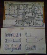
I went into the filing cabinet and found my old notes and sketches. It seems I had the Quad owners manual before the actual build. One look at the crazy template I made for the PCB layout says I was lucky the amplifier worked. I don't miss the days of tape and magic markers for teching a PCB.
Attachments
Grounding questions
Thanks to everyone above. I've got a 2x30V toroidal and a prebuilt power supply. I'm a bit stuck with the grounding. I appreciate these are basic questions but having read through several articles I'm still not sure.
I've followed the below diagram found at Building a Gainclone chip amp power supply.
1)My PSU has a ground terminal next to the AC inputs. Should I connect this to the one that I've created by connecting the 0V and 18V secondaries (orange and red)?
2) Where do I run my signal ground to?
3) Where do I run the ground connection from the amplifier board?
4) Where do I earth my Chassis to?
Attachments

Have you looked at original Quad 405 schematics yet?
http://www.saturn-sound.com/images - cct dia/quad 405 mk1- stereo power amplifier - cct dia'.jpg
http://www.saturn-sound.com/images ...later - stereo power amplifier - cct dia'.jpg
General guidelines for wiring up an audio amplifier power supply (and a lot more) are here: Power Supply Wiring Guidelines
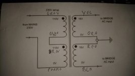
On the Transformer Primaries, join the violet and grey. That leaves the brn and blu available to connect to mains. Brn is Live and Blu is Neutral.Thanks to everyone above. I've got a 2x30V toroidal and a prebuilt power supply. I'm a bit stuck with the grounding. I appreciate these are basic questions but having read through several articles I'm still not sure.
I've followed the below diagram found at Building a Gainclone chip amp power supply.
1)My PSU has a ground terminal next to the AC inputs. Should I connect this to the one that I've created by connecting the 0V and 18V secondaries (orange and red)?
2) Where do I run my signal ground to?
3) Where do I run the ground connection from the amplifier board?
4) Where do I earth my Chassis to?
When you come to assembling the PSU remember to twist your flow and return pairs.
The three wires into the PCB terminal block are a twisted triplet (not braided).
Last edited:
Have you looked at original Quad 405 schematics yet?
http://www.saturn-sound.com/images - cct dia/quad 405 mk1- stereo power amplifier - cct dia'.jpg
http://www.saturn-sound.com/images ...later - stereo power amplifier - cct dia'.jpg
General guidelines for wiring up an audio amplifier power supply (and a lot more) are here: Power Supply Wiring Guidelines
In any case, do not connect the amplifier's chassis as shown here Power Supply Wiring Guidelines, see picture, if only you personally, not grounding into the earth this ground loop. This particularly applies to those. who lives in apartments of high-rise buildings. There is a ground loop has no connection with the earth, and only with a power transformer substation ~110 volts. It can have capacity in relation to the physical earth, such as radiators and water pipes, which are physically grounded at least through the water. The case could end up cold heels and a tag on his toe.
If you live in a private house, ground the third pin of outlets on their own, or disconnect the third contact with the chassis of the amplifier!!!
Last edited by a moderator:
Further wiring questions
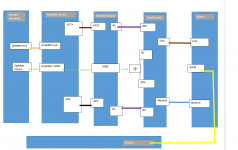
So I've read through the sources recommended, hoping someone can please confirm that the wiring for me before testing. I've made a simplified diagram of the wiring, and have already made the solid connections illustrated.
It looks like what I should do is make the dotted green connection, but this feels wrong as I'm making a physical connection between a speaker terminal and a transformer secondary.
As always, help very much appreciated!
Attachments
You need smoothing capacitors between the rectifier and the amplifier.
The transformer Centre Tap connects to the Input of the smoothing caps.
The output of the smoothing caps becomes the ultimate connection for the Amplifier Power Ground and the Speaker Return.
The transformer Centre Tap connects to the Input of the smoothing caps.
The output of the smoothing caps becomes the ultimate connection for the Amplifier Power Ground and the Speaker Return.
DOGC by Dr. Bora Jagodic
Hi guys,
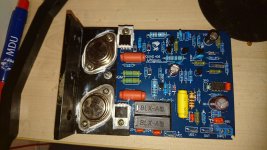
very good implementation of Quad´s current dumping system is made by Dr. Borivoje Jagodic in his DOGC-MK3, DOGC-H and IOTA-CD amplifiers. More details are on his website:
:::Borina Amaterska Svastara:::
I have made DOGC and its sound quality is exceptional!
Definately check it out.
Hi guys,
very good implementation of Quad´s current dumping system is made by Dr. Borivoje Jagodic in his DOGC-MK3, DOGC-H and IOTA-CD amplifiers. More details are on his website:
:::Borina Amaterska Svastara:::
I have made DOGC and its sound quality is exceptional!
Definately check it out.
- Home
- Amplifiers
- Solid State
- QUAD 405 clone