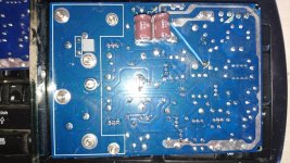
Good news, the amplifier is up and running with no damage. The only other thing it might have been was an electro-static shock, if you had picked up static while dismantling and reassembling - an ESD wrist-strap would prevent that. Looking at your previous picture, the yellow link wire probably is part of the circuit and needs to be connected. Your boards were previous to my version and they copied the original faithfully, even including this wiring link that was on the 1976 version. It is part of the -VCC current-limiting circuit that you will remove anyway if you are going to modify. The Zobel Network correction is exactly as you have shown, just isolate or cut around the leg of R39 (its currently on the signal GND) and connect it to the power GND as you have shown. Previous DIYers have blown tweeters or smoked boards by forgetting to correct this error.
Magic smoke
Hmm, now I've got something to smoke!
Not a great result, but it was at least a cheap learning exercise.
Thanks
geoff
Hmm, now I've got something to smoke!
Not a great result, but it was at least a cheap learning exercise.
Thanks
geoff
Well, its not because you haven't found out what is wrong. The Zobel network error correction wont cause that. If your output oscillates, R39 will get very hot as it dumps the high frequency signal to GND - it doesn't usually survive for more than a few seconds. Find out what has damaged with a view to replacing. More likely, you need to make sure your grounding is correct.
A friend of mine who has bought two LJM Quad 405 clone boards asks me to quickly verify them.
I used a +/-30 V regulated power supply.
As the original schematics, the input LM301 has no local decoupling cap.
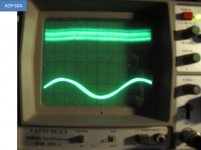
Using 10 kHz square waves, 160 kHz input low pass filtered, I did not find oscillations neither with a resistive load of 8 Ohm nor with pure capacitve loads of 2.2 µF and then 100 nF. Just some overshoot.
Distortion at 1 kHz, 4 Vrms was about 0.01%.
I did not check if the layout was in accodance with what I consider to be the good rules.
I used a +/-30 V regulated power supply.
As the original schematics, the input LM301 has no local decoupling cap.
Using 10 kHz square waves, 160 kHz input low pass filtered, I did not find oscillations neither with a resistive load of 8 Ohm nor with pure capacitve loads of 2.2 µF and then 100 nF. Just some overshoot.
Distortion at 1 kHz, 4 Vrms was about 0.01%.
I did not check if the layout was in accodance with what I consider to be the good rules.
Thanks to Roclite for his post here, it save me some trouble.
I didn't notice the presence of R2 and put only one ground connection as i am used in other amplifiers... and got a radio transmitter with 40V voltage swing.
The beast is pretty sensitive to oscillation and I went into additionnal decoupling but went into more trouble.
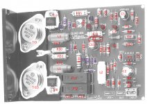
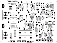
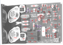
To apply some mods I found useful to get a board view with component ref.. it might be usefull for others (cf jpg attached).
Main trouble I had was the stability of power on AOP the positive railwas more +9V than +15V, even changing the Zener for a new 1.3W 15V was not enough even with a low power fet AOP. I did try the solution of a 24V zener + LM7815/LM7915 to get perfect symetric supply on AOP. With this i can even use a discrete bipolar AOP from Audio-GD... but the 24v zener gets hot fast.
At the end i still have 200mV @ 160KHz on the speakers... guess what i'm on SMPS power supply and i was using the aux output to drive the relay protection board but on +12V only and then the load is asymetric the ripple is not the same on +45V/-45V main output and it's visible on output.
removing the aux connection switching noise ripple on main supply is down at 40mV @ 160khz ... on speaker output noise is down at 10mV
but I don't know how to get rid of this...
LC filter on power Rails ? or acceptable ?
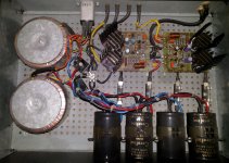
after a week of work every night after work, got 1rst music in speakers... but not a clean design.
Jean-Claude
I didn't notice the presence of R2 and put only one ground connection as i am used in other amplifiers... and got a radio transmitter with 40V voltage swing.
The beast is pretty sensitive to oscillation and I went into additionnal decoupling but went into more trouble.
To apply some mods I found useful to get a board view with component ref.. it might be usefull for others (cf jpg attached).
Main trouble I had was the stability of power on AOP the positive railwas more +9V than +15V, even changing the Zener for a new 1.3W 15V was not enough even with a low power fet AOP. I did try the solution of a 24V zener + LM7815/LM7915 to get perfect symetric supply on AOP. With this i can even use a discrete bipolar AOP from Audio-GD... but the 24v zener gets hot fast.
At the end i still have 200mV @ 160KHz on the speakers... guess what i'm on SMPS power supply and i was using the aux output to drive the relay protection board but on +12V only and then the load is asymetric the ripple is not the same on +45V/-45V main output and it's visible on output.
removing the aux connection switching noise ripple on main supply is down at 40mV @ 160khz ... on speaker output noise is down at 10mV
but I don't know how to get rid of this...
LC filter on power Rails ? or acceptable ?
after a week of work every night after work, got 1rst music in speakers... but not a clean design.
Jean-Claude
Attachments

hi Stuart,
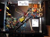
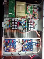
Added a little 12V transformer for protection board...
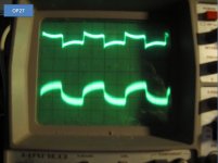
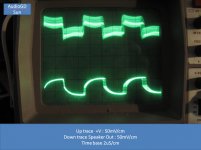
Yes, ripple is mainly coming from PSU switching via +V -V rails
Traces are not sharp as there is also a little of 50Hz
Except with OP604 where it start to oscillate by itself at onother freq
a 50mH self with the 470uF added on board should filter this
A shield around the PSU board ?
Project i've seen with SMPS are not going into those heavy solutions...
Going to make a break next week !😎
rgds
Jean-Claude
Added a little 12V transformer for protection board...
Yes, ripple is mainly coming from PSU switching via +V -V rails
Traces are not sharp as there is also a little of 50Hz
Except with OP604 where it start to oscillate by itself at onother freq
a 50mH self with the 470uF added on board should filter this
A shield around the PSU board ?
Project i've seen with SMPS are not going into those heavy solutions...
Going to make a break next week !😎
rgds
Jean-Claude
Attachments
Hi Jice, I think there might be a typo in your pcb / component picture, you appear to have C7 twice? I think the one at the top of the board should be C11.
I've been trying to come up with something similar, but my board is a bit different than yours...
I've been trying to come up with something similar, but my board is a bit different than yours...
Attachments
Hi guys! First I wanna say that everything you add here is great and very helpful to enthusiasts around the globe! roclite I want to achieve the same great sound you got and I like that you basically tested 3 different version of 405. If this is the best we can get out of Quad 405 should we make it official? A schematic, list of elements used with their specifications, pictures like the one Jice78 posted, including of the power block. Something that can make replicating the project easy/accessible. I will be honest, I'm 33 and amateur in electronics (but very good at a lotta other things, including getting projects done) and keith-snook site is just getting me confused, it is too high level talk for me. All the possible changes and options are cool, but what is the best configuration? Where is the schematic, list of all used elements, pictures ect. I ordered 4 405 kits from ebay (2pcs QUAD405 125W+125W power amplifier kit dual 2.0 channel for HIFI DIY) US $29.95 each. And my the plan is to build 1 6channel amp for me and 1 2channel for my dad. He is electronics engineer so I will be getting help. I will be aiming for very simple design and wont need more than 60% of the volume power, so smaller power supply?? will add possibility to turn channels off by pairs or per channel. The 6channel will be basically used as 5.1 surround, controlled exclusively by computer. The .1 in 5.1 is the bass and computers can do good job at cutting at 80hz, the rest 5 will be the front and rear left/right and center. I'm contemplating even not having potentiometers, if the max volume by mistake wont give heart attack to somebody it should be safe. If I pull it off well with the first one, I will make another with 6channels, this time will be used as 3 stereo pairs for my speakers in kitchen, bathroom and garage(already existing and playing through other amp). I will take a lot of pictures and try to document into a full guide kit for noobs like me. So can you guys help? Can we collect all the info in one place? http://www.diyaudio.com/forums/members/roclite.html
Hi all ! i am just finishing putting together a pair of metal type t03 ? 405 boards from china and have been reading through all the threads i can find here on the 405s, great forum by the way 😎 and from what i have read they need a bit of modifying, an earth link and a bit of the track cut which looks quite straight forward, and one of the transistors is marked on the board the wrong way round although i cant find which one ??? can anyone please clarify if i have got this right ? the boards are marked 2004-2013 so i am not sure if it has been fixed yet ?
The last amp i built was an old maplins kit more than 20years ago a 100wpc mosfet similar to the 405 but simpler and a pre amp for it out of a book, on stripboard its still going strong part of my surround system.
The last amp i built was an old maplins kit more than 20years ago a 100wpc mosfet similar to the 405 but simpler and a pre amp for it out of a book, on stripboard its still going strong part of my surround system.
Ok i got the ground sorted and was wrong about the transistor reversed !
I have a 625 va dual 40v transformer, will 56v be too much voltage for these boards ?
I have a 625 va dual 40v transformer, will 56v be too much voltage for these boards ?
Hello all,
I built a number of Maplin GA28F amps about 25 years ago which performed brilliantly and flawlessly. Friends and various bands I played in ended-up with most of them but I kept one and have been using it off-and-on ever since.
When I moved house, one of the amplifier boards jumped off the plastic stands unbeknown to me, and when I tried using it, it blew. I was amazed to learn Maplin no longer sells this board any more, and that second hand ones go for quite incredible prices on Ebay.
Whilst looking in Ebay, I became aware of the Chinese Quad clones, and thought that maybe it was time to build something more "pro", so I ordered a couple of those Quad clones, a 300VA toroidal, a pre-built PSU (6x 10,000uF caps and a delayed speaker switch-on), some ancillaries and one of the clone Quad 405 cases which was horribly expensive but looks wonderful from the pictures (I'm still waiting for that to turn up).
My intention is to build 2x complete 405s and then to have a go at building a pair of Rogers LS5/8 speakers. I know the particular bass driver is no longer available but there are 12" polypropylene drivers available and "versions" of the Audax tweeter (which may have less than stellar low frequency response), both of which I hope can be tailored with active crossover boards - I think I will end up with enough room in the new Quad case.
Anyway, I'll post pics as I progress although at the moment I'm still waiting on the postman for a number of critical components. In the meantime, I've adapted the Quad boards to correct the Zobel issue and I've just learned that I need a ground-breaker circuit - both with huge thanks to roclite.
While I'm waiting, I decided to build a self-powered subwoofer for my son, and use the working Maplin amp in that.
My Maplin amp before I cannibalised it:
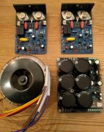
My growing collection of Quad components:
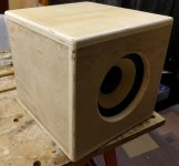
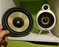
My son's subwoofer project. The intention is to paint it white to match the Scandyna speakers we has. I started off buying an 8 inch kevlar driver to match the Scandynas. The colour's not an accurate match but it'll do:
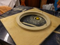
Bought a pre-cut speaker ring from Ebay to use as a template to guide the router:
Came out satisfactorily :
After a "first cut" sanding, it's starting to look pretty good:
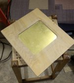
The back panel rebated into the back baffle. I have an edging strip that forms a nice seal (not shown):
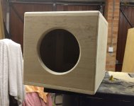
So far - awaiting smooth-fill, final sanding and painting:
Anyway - sorry for thread divergence. I'll stick to the Quads in future updates.
I built a number of Maplin GA28F amps about 25 years ago which performed brilliantly and flawlessly. Friends and various bands I played in ended-up with most of them but I kept one and have been using it off-and-on ever since.
When I moved house, one of the amplifier boards jumped off the plastic stands unbeknown to me, and when I tried using it, it blew. I was amazed to learn Maplin no longer sells this board any more, and that second hand ones go for quite incredible prices on Ebay.
Whilst looking in Ebay, I became aware of the Chinese Quad clones, and thought that maybe it was time to build something more "pro", so I ordered a couple of those Quad clones, a 300VA toroidal, a pre-built PSU (6x 10,000uF caps and a delayed speaker switch-on), some ancillaries and one of the clone Quad 405 cases which was horribly expensive but looks wonderful from the pictures (I'm still waiting for that to turn up).
My intention is to build 2x complete 405s and then to have a go at building a pair of Rogers LS5/8 speakers. I know the particular bass driver is no longer available but there are 12" polypropylene drivers available and "versions" of the Audax tweeter (which may have less than stellar low frequency response), both of which I hope can be tailored with active crossover boards - I think I will end up with enough room in the new Quad case.
Anyway, I'll post pics as I progress although at the moment I'm still waiting on the postman for a number of critical components. In the meantime, I've adapted the Quad boards to correct the Zobel issue and I've just learned that I need a ground-breaker circuit - both with huge thanks to roclite.
While I'm waiting, I decided to build a self-powered subwoofer for my son, and use the working Maplin amp in that.
My Maplin amp before I cannibalised it:
An externally hosted image should be here but it was not working when we last tested it.
My growing collection of Quad components:
An externally hosted image should be here but it was not working when we last tested it.
My son's subwoofer project. The intention is to paint it white to match the Scandyna speakers we has. I started off buying an 8 inch kevlar driver to match the Scandynas. The colour's not an accurate match but it'll do:
An externally hosted image should be here but it was not working when we last tested it.
Bought a pre-cut speaker ring from Ebay to use as a template to guide the router:
An externally hosted image should be here but it was not working when we last tested it.
Came out satisfactorily :
An externally hosted image should be here but it was not working when we last tested it.
After a "first cut" sanding, it's starting to look pretty good:
An externally hosted image should be here but it was not working when we last tested it.
The back panel rebated into the back baffle. I have an edging strip that forms a nice seal (not shown):
An externally hosted image should be here but it was not working when we last tested it.
So far - awaiting smooth-fill, final sanding and painting:
An externally hosted image should be here but it was not working when we last tested it.
Anyway - sorry for thread divergence. I'll stick to the Quads in future updates.
If you right click them and select 'open in new tab' or whatever your browser options are then they will open but its much better to attach them directly to the forum.
Will your pictures still be here in 6 weeks or 6 months ? or six years. They will if you attach them.
Will your pictures still be here in 6 weeks or 6 months ? or six years. They will if you attach them.
Now with pics attached
Yes, of course. Thanks for the advice. Some forums prefer you to host elsewhere but I agree with you that the links may eventually lead to nothing. So with that in mind, please find attached all the pics linked to above, in the intended order.
Yes, of course. Thanks for the advice. Some forums prefer you to host elsewhere but I agree with you that the links may eventually lead to nothing. So with that in mind, please find attached all the pics linked to above, in the intended order.
Attachments
405 clone first build
Hi everyone, I'm just about to start building a 405 clone. I previously had a lm3886 chipamp running but the (ancient) transformer gave up. Looking to upgrade I bought two 405 clone kits through eBay from a seller who builds clones and claims to have corrected the grounding error. Three questions I hope you can help me with:
1) Has the grounding correction done right?
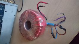
2) Will a 27.5v 300va transformer be ok? Gives ~38.5V after the rectifier. It doesn't have a 0V wire, as compared to the previous transformer I had which was a 25-0-25. Picture attached.
3) I have two of the above transformers. Is there a realistic benefit to a dual mono configuration? Any big downsides to this other than the weight and size?
Any help is much appreciated
Hi everyone, I'm just about to start building a 405 clone. I previously had a lm3886 chipamp running but the (ancient) transformer gave up. Looking to upgrade I bought two 405 clone kits through eBay from a seller who builds clones and claims to have corrected the grounding error. Three questions I hope you can help me with:
1) Has the grounding correction done right?
2) Will a 27.5v 300va transformer be ok? Gives ~38.5V after the rectifier. It doesn't have a 0V wire, as compared to the previous transformer I had which was a 25-0-25. Picture attached.
3) I have two of the above transformers. Is there a realistic benefit to a dual mono configuration? Any big downsides to this other than the weight and size?
Any help is much appreciated
Attachments
1/ No idea 😉 I don't know what the original problem was.
2/ Your single winding tranny will only generate a single rail of 38 volts DC. I would imagine the Quad clone requires a dual 'minus, ground, plus' configuration which is where the tranny with a centre tap is needed. The original Quad used -/+50 volts (so 100v in total)
3/ If those are the only trannys you have then you will need both to generate a dual rail supply. Dual mono has many advantages but you can't do that with what you have.
 Thanks Mooly.
What would be the effect of using +/-38v DC instead of 50V? Lacking volume, or bass,or not working at all? The ebay listing for similar modules suggests an input of +/-30VAC to +/-50VAC
I've been looking for a guide on making a dual rail using two transformers but have had no luck.
My transformers have a red and a black wire on AC secondaries. My rectifier has 3 terminals marker 26v, GND, 26v (but components are all rated at 50V or above). Can I run black leads from both transformers into GND and a red from each into the each of the 26V terminals? Or will I end up with shorting and fires?
Also from what I've been reading, wouldn't one hefty transformer, but using dual rectifiers and large capacitors give the benefits of dual mono? I'm thinking about it in terms of one channel sapping power from the other
Last edited:
- Home
- Amplifiers
- Solid State
- QUAD 405 clone