LJM clone 405 boards are for split supplies although they use the oldest (first) 405 circuit version.
I am about to build these clones, the plastic package type to put into an original Quad405 case and transformer from your comment above are you saying these wont work using the original connections and transformer?
sorry if its a dumb question
cheers
Hi guys! First I wanna say that everything you add here is great and very helpful to enthusiasts around the globe! roclite I want to achieve the same great sound you got and I like that you basically tested 3 different version of 405. If this is the best we can get out of Quad 405 should we make it official? A schematic, list of elements used with their specifications, pictures like the one Jice78 posted, including of the power block. Something that can make replicating the project easy/accessible. I will be honest, I'm 33 and amateur in electronics (but very good at a lotta other things, including getting projects done) and keith-snook site is just getting me confused, it is too high level talk for me. All the possible changes and options are cool, but what is the best configuration? Where is the schematic, list of all used elements, pictures ect. I ordered 4 405 kits from ebay (2pcs QUAD405 125W+125W power amplifier kit dual 2.0 channel for HIFI DIY) US $29.95 each. And my the plan is to build 1 6channel amp for me and 1 2channel for my dad. He is electronics engineer so I will be getting help. I will be aiming for very simple design and wont need more than 60% of the volume power, so smaller power supply?? will add possibility to turn channels off by pairs or per channel. The 6channel will be basically used as 5.1 surround, controlled exclusively by computer. The .1 in 5.1 is the bass and computers can do good job at cutting at 80hz, the rest 5 will be the front and rear left/right and center. I'm contemplating even not having potentiometers, if the max volume by mistake wont give heart attack to somebody it should be safe. If I pull it off well with the first one, I will make another with 6channels, this time will be used as 3 stereo pairs for my speakers in kitchen, bathroom and garage(already existing and playing through other amp). I will take a lot of pictures and try to document into a full guide kit for noobs like me. So can you guys help? Can we collect all the info in one place?
Hi, Did you in fact ever manage to pull all the info together? I am thinking of building the clone and would love to be able to access such info.
cheers
Hello!
I have see on eBay and Aliexpress a new 405 clone board. They claim to be a 405-2 version. Seems to be a new designed PCB with better tracks and grounds.
Does someone know this new version?
50 v 100 w QUAD405 2 termine conseil stereo canal 2 conseils dans Amplificateur de Electronique sur AliExpress.com | Alibaba Group
Attachments
Last edited:
Hi!
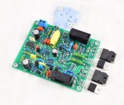
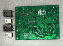
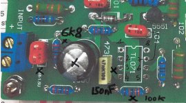
Just to write a little about the Chinese kits I finally assembled and modded.
The kits works fine but the input stage need to be adapted for modern equipment. It stay with 0.7V sensibility from original design.
3 components needed to be changed for 1.5V sensibility. See pictures.
You also need to change the four 560 2W green resistors close to the power transistor. The stock resistors are stick to the pcb. Too hot -> 72°C box closed. Use 3W and it is necessary to raise them by 1cm from pcb.
Optionally, change opamps, electronics caps and input caps.
I replaced the stock TLs with OPA627.
Nice warm sound and dynamic (It use a Switching DC Power Supply).
Cheers,
Attachments
Last edited:
Is that a link on pin 7 of the ic for using the OPA627 stef ?
Iv'e got a quad 34 pre amp so i can leave the 0.7v as is, i will take your advice with the resistors thanks.
Iv'e got a quad 34 pre amp so i can leave the 0.7v as is, i will take your advice with the resistors thanks.
Hi!
The circuit for the opamp is the same as in the original circuit except the C3 3.3PF between 1 and 8 pins that do not exist.
The circuit for the opamp is the same as in the original circuit except the C3 3.3PF between 1 and 8 pins that do not exist.
Do you have a schematic of this kit? It does not look like the original 405 or 405-2. Does it have the clamp protection circuit?
No, I don't have it. May be ask LJM.
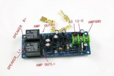
I used an external protection circuit.
Assembled LJM Audio stereo speaker protection board | eBay
I used an external protection circuit.
Assembled LJM Audio stereo speaker protection board | eBay
Attachments
I would think tip42c is rated to low at 100v for this amplifier as the rails are 56v.
MJE15031 can handle voltage but is a lot faster.
Best part of 405 is the very low hum pickup of the chassis.
I have been thinking of picking up a chassis + transformer and put in a better amp.
MJE15031 can handle voltage but is a lot faster.
Best part of 405 is the very low hum pickup of the chassis.
I have been thinking of picking up a chassis + transformer and put in a better amp.
Last edited:
The Max is +- 50v same as the original 405 , i got hold of a chassis im using with some burnt out net audio 405 3 boards which i would like to fix, but i can't get hold of a schematic, the boards are different from a 405 and look like they have been mucked about with and have different links and components on each one, i will try the clones and see how they sound.
I haven't found a schematic for these 405 2 boards either
I haven't found a schematic for these 405 2 boards either
Lot of schematics on Keith Snook's homepage, http://keith-snook.info/amplifier-hifi-schematics/QUAD 405 schematic evolution.pdf
There is also a way to do without the clamp protection circuitry. I recommend going through Keith Snook's Writing. I have been hoping for someone to make new PCBs following his 405-3 with the active ground circuit.
www.keith-snook.info/quad-stuff/QUAD-405-Dual-Mono-PSU/QUAD-402-2-Dual-PSU-fitted.png
Last edited:
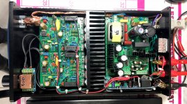
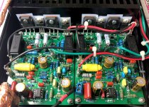
Edit // did you connect your copper foil to ground to ensure a proper shielding?
Perhaps you can move your switch on the back and put some light to fill the front hole?
I assembled an Mx50x2 and an Mx50SE with the same psu but, as I do not use a potentiometer, I put psu on front and amps to the back to shorten signal path.
Both are dead silent on my 93db speakers.
Did you connect earth (right upper screw) and ground (left lower screw) on your psu?
I'm wayting for the same Quad board and will apply the gain mod you spoke above.
Last edited:
No luck. If I move the switch of 6mm, no more hums.
The 12V on the PSU is weak. II changed some of the caps for a better smoothing. For the DC card, I took the +12V before the 7812 on the psu to have more voltage.
I've done this. See scan. The box is connected from one of the screws but I've forgot which one.
Not sure, it's ok.
The 12V on the PSU is weak. II changed some of the caps for a better smoothing. For the DC card, I took the +12V before the 7812 on the psu to have more voltage.
I've done this. See scan. The box is connected from one of the screws but I've forgot which one.
Not sure, it's ok.
Attachments
Last edited:
You have wired the psu different to what i would have thought ? i would connect the mains earth to ac side and case, and the grounds to dc or 0v end of psu ? it looks as though yours is all on the ac end , it must be right though if it works ??No luck. If I move the switch of 6mm, no more hums.
The 12V on the PSU is weak. II changed some of the caps for a better smoothing. For the DC card, I took the +12V before the 7812 on the psu to have more voltage.
I've done this. See scan. The box is connected from one of the screws but I've forgot which one.
Not sure, it's ok.
Yeah, earth side must be connected to ac and case to ensure input filter is working properly and case shielding.
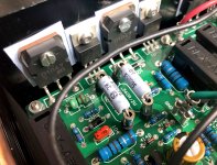
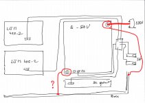
Again me.
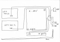
Is this ok ?
I made a change.
The case is connected to AC earth through the screw and the spacer.
But currently, the DC ground is also connected to the case through the screw and the spacer.
Is this ok ?
I made a change.
The case is connected to AC earth through the screw and the spacer.
But currently, the DC ground is also connected to the case through the screw and the spacer.
Attachments
Last edited:
Ac hole to the case via metal spacer is ok, but you may also connect it to your ac socket.
I'm sorry but your drawing is to imprecise for me.
Your ac socket have 3 pin, L N and Earth.
L and N go to psu input (I guess L to fuse side)
Earth to the upper right screw on your picture to ensure input filter is working properly.
I'm sorry but your drawing is to imprecise for me.
Your ac socket have 3 pin, L N and Earth.
L and N go to psu input (I guess L to fuse side)
Earth to the upper right screw on your picture to ensure input filter is working properly.
Hi!
It's done as you said. The upper right screw is directly connected to the AC outlet earth. It was connected to the DC ground before.
The lower left hole is connected to the case too. Not a problem?
As it seem to be the DC ground (same as 0v).
The copper shield around the AC cables is also connected to the case (on one side only).
Hums seems much lower without have moved the power switch. I'll do more test tonight.
Will try to draw a news schematic. 😉
Last edited:
- Home
- Amplifiers
- Solid State
- QUAD 405 clone