Let me quote Keith's text here for all to see. I take it as well reasoned and proven, from an experienced engineer who knows what he is talking about. I don't have his expertise and don't even have the clone here to experiment with. However, I still have a couple of pairs of PCBs with parts so perhaps I'll get the time to change that.
"If you feel you must change the op–amp consider the input bias current specification which generally gets worse as gain bandwidth product (GBWP) increases ~ FET input devices like TLE2071, OP134 and OPA604 are all good for audio and have very low input bias current required for the low output voltage offset in this design
The QUAD 405 op~amp output operates in Class A ~ There is little or no benefit fitting some modern "distortion cancelling" op~amps that "do voodoo" around the zero crossing point ~ IC1 output never crosses zero and the rest of the circuit is effectively Class A including the Dumpers as they are in the Bridge with the Class A stage
The "new kid on the block" the National LME49710 may be a replacement option with only 7nA bias current but it has a high GBWP which could make it unstable and you will not get the published specification in the 405 circuit ~ Many application circuits for these "new" op–amps show current sinks connected from output to ground so the device output does not cross zero and measures better as would almost any op–amp
Beware of bipolar input devices like the NE5534 which is often substituted in the QUAD 405 ~ The NE5534 and the dual NE5532 etc. are very good op–amps and were probably used to produce much of the music you listen too but they may give an output offset of 150mV when used in the 405. "
I read some of the chat and imaginative claims on forums discussing Quad mods and the reasoning for trying a non-audio precision amp like OP27. Personally, I don't think rolling opamps is wise just because there is a socket and and you can. There could be slight improvement but I understand it will be insignificant considering the inherent noise level. The full mod. to non-inverting, perhaps wired on a small daughter board, would seem a much more promising and worthwhile project.
Hi Umut,
I purchased a pair of these 405 clones too with the intention of using them to try out all the documented Quad 405 mods (Keith Snook and others) and build them into a clone 405 amp, with better power supply, connectors etc. However, the first package I received from seller was in kit form and not fully assembled, as I had ordered. In meantime, I saw and bought a cheap Quad 405 from ebay and started to work on that instead. The LJM seller has now sent me the fully assembled boards and has not asked for the kit back so I have 2 sets of the LJM Quad 405, one assembled and one in kit form.
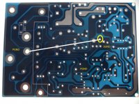
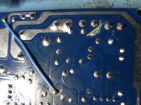
I am going to do what I intended and modify and test the clone boards first before I transfer the change across to the genuine 405 amplifier boards. That way, there is less chance of damaging the real boards with soldering/re-soldering. So I am able to share some information on this LJM board that you others may find interesting if they want to do the same thing. Firstly, all current versions of the LJM board have the well-known Quad 405 Zobel network error - the Zobel network is connected to SGND (signal) when it should be connected to PGND (power). I used an improvised light-box to photo the bare PCB. I have marked on it the SGND and PGND. To separate the Zobel network, cut around the pcb pad to isolate the resistor leg connection OR lift the resistor leg. Wire the resistor leg to the PGND near the heatsink mounting hole as shown in white.
As Ian says, Keith wrote there was not much point in rolling op-amps in the original Quad 405 input op-amp configuration due to the circuit design. However, Keith provided a well-documented mod to change the input op-amp configuration to non-inverting which might be worthwhile and give definite sonic improvements with newer up-to-date op-amps. I intend to do this modification to roll op-amps for my own preference. I also intend to incorporate other mods in line with Keith's revision to DCD Mod-3 level (check Keith Snook web-site for diagram). His revision removes several components from the board which simplifies the build considerably and increases reliability. I also want to incorporate a few of my own changes:
a) Replace the input C1 680nF with better quality, higher value
b) Consider isolating the output connection away from the input.
b) may or may not be causing an oscillation problem but the
replacement transistors on the LJM (MJ15024G) are much wider
band-width than the original design transistors so its more susceptible
to oscillation. This might be more relevant coupled with changing other
components.
I purchased a pair of these 405 clones too with the intention of using them to try out all the documented Quad 405 mods (Keith Snook and others) and build them into a clone 405 amp, with better power supply, connectors etc. However, the first package I received from seller was in kit form and not fully assembled, as I had ordered. In meantime, I saw and bought a cheap Quad 405 from ebay and started to work on that instead. The LJM seller has now sent me the fully assembled boards and has not asked for the kit back so I have 2 sets of the LJM Quad 405, one assembled and one in kit form.
I am going to do what I intended and modify and test the clone boards first before I transfer the change across to the genuine 405 amplifier boards. That way, there is less chance of damaging the real boards with soldering/re-soldering. So I am able to share some information on this LJM board that you others may find interesting if they want to do the same thing. Firstly, all current versions of the LJM board have the well-known Quad 405 Zobel network error - the Zobel network is connected to SGND (signal) when it should be connected to PGND (power). I used an improvised light-box to photo the bare PCB. I have marked on it the SGND and PGND. To separate the Zobel network, cut around the pcb pad to isolate the resistor leg connection OR lift the resistor leg. Wire the resistor leg to the PGND near the heatsink mounting hole as shown in white.
As Ian says, Keith wrote there was not much point in rolling op-amps in the original Quad 405 input op-amp configuration due to the circuit design. However, Keith provided a well-documented mod to change the input op-amp configuration to non-inverting which might be worthwhile and give definite sonic improvements with newer up-to-date op-amps. I intend to do this modification to roll op-amps for my own preference. I also intend to incorporate other mods in line with Keith's revision to DCD Mod-3 level (check Keith Snook web-site for diagram). His revision removes several components from the board which simplifies the build considerably and increases reliability. I also want to incorporate a few of my own changes:
a) Replace the input C1 680nF with better quality, higher value
b) Consider isolating the output connection away from the input.
b) may or may not be causing an oscillation problem but the
replacement transistors on the LJM (MJ15024G) are much wider
band-width than the original design transistors so its more susceptible
to oscillation. This might be more relevant coupled with changing other
components.
Attachments

Thanks for the info Roger. I have been listening to my original 405 for some weeks now after a basic re-cap (DC supply and amp modules) and think it sounds amazing. It will be very interesting to find out if a modded clone 405 sounds any better. I think a lot depends on your source and I use CD coax/Bifrost DAC/Passive SYS volume. Its not perfect but despite the 405's vintage (circa 1978), it sounds remarkably good to my ears. Might be a case of beneficial system balancing but at the end of the day its the sound coming out of the speakers that matters.
LJM clone Quad 405 (TO3 MJ15024G version)
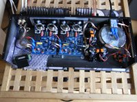
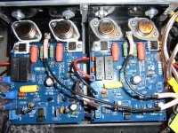
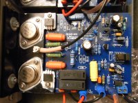
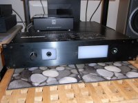
I have finally built my LJM clone 405 amplifier, using two pre-assembled modules bought from eBay for £36. I have it wired up for listening tests, minus the front panel which needs work to fit the volume control and mains ON/OFF switch (pic attached).
First listening impressions. Its good. Its very, very good. IMO compared to the original 405, better soundstage, dynamics, depth and clarity. Of course, its not a standard Quad 405, only the amplifier modules resemble the original version and I have different power supply (Antrim 225VA Toroidal plus 20,000uF/rail filter caps) and an Alps Black Beauty volume control. But it "sounds" like my original 405 in many respects, especially in the upper frequencies - rather brittle, harsh treble probably a characteristic of the LM301A op-amp input stage design.
In terms of modifications, I did very little to the LJM Quad 405 modules:
a) Corrected the Zobel network grounding error (see previous post)
b) Trimmed back the OUTPUT pcb track adjacent to the SIGNAL track to increase physical separation. This may not have been necessary at all but it was very easy to do pre-assembly, to decrease the likelihood of an oscillation problem.
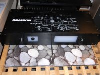
All the amplifier kit was bought from eBay. You may recognise the 19" rack mounting case that came from a dead Samson Servo 170 amp (£30). I bet the working Samson 170 never sounded this good, ever! 😉. All in all, I spent about £100 on components.
I am going to finish off the enclosure and will continue to audition the new amplifier with the rest of my music collection. Who knows, I might prefer the sound of the clone to the original, in which case, keep your eyes open on eBay 🙂
I have finally built my LJM clone 405 amplifier, using two pre-assembled modules bought from eBay for £36. I have it wired up for listening tests, minus the front panel which needs work to fit the volume control and mains ON/OFF switch (pic attached).
First listening impressions. Its good. Its very, very good. IMO compared to the original 405, better soundstage, dynamics, depth and clarity. Of course, its not a standard Quad 405, only the amplifier modules resemble the original version and I have different power supply (Antrim 225VA Toroidal plus 20,000uF/rail filter caps) and an Alps Black Beauty volume control. But it "sounds" like my original 405 in many respects, especially in the upper frequencies - rather brittle, harsh treble probably a characteristic of the LM301A op-amp input stage design.
In terms of modifications, I did very little to the LJM Quad 405 modules:
a) Corrected the Zobel network grounding error (see previous post)
b) Trimmed back the OUTPUT pcb track adjacent to the SIGNAL track to increase physical separation. This may not have been necessary at all but it was very easy to do pre-assembly, to decrease the likelihood of an oscillation problem.
All the amplifier kit was bought from eBay. You may recognise the 19" rack mounting case that came from a dead Samson Servo 170 amp (£30). I bet the working Samson 170 never sounded this good, ever! 😉. All in all, I spent about £100 on components.
I am going to finish off the enclosure and will continue to audition the new amplifier with the rest of my music collection. Who knows, I might prefer the sound of the clone to the original, in which case, keep your eyes open on eBay 🙂
Attachments

Hi Mooly,
Yes, it uses LM301A although being Chinese manufactured there could be something completely different beneath the package😉. The clone board design is based on Quad 405 M12333 Iss 3, one of the early Quad implementations. Others have already commented that the designer (LJM) could have copied a much later version of the design, with errors removed and possible sonic benefits from an optimised design.
Yes, it uses LM301A although being Chinese manufactured there could be something completely different beneath the package😉. The clone board design is based on Quad 405 M12333 Iss 3, one of the early Quad implementations. Others have already commented that the designer (LJM) could have copied a much later version of the design, with errors removed and possible sonic benefits from an optimised design.
Interesting, thanks. Perhaps the LM301 would be one real area to investigate improving on.
Long time ago I owned a 405 (type 1) and changed the LM301 into OP27. It did sound a bit better... definition improved slightly...
Yes, there are several well-documented up-dates to the design that go above and beyond rolling input op-amps i.e. changing op-amp configuration to non-inverting and removing several unnecessary noise-producing components. I like the sound of the clone so much, I might keep it as is and build a second clone using an identical LJM Quad 405 self-assembly kit that I already have. It makes more sense to do the changes to the kit version. I could then compare to the original LJM clone and the standard Quad 405. I will up-date this thread with more results and will be happy to help anyone who is going down a similar route 🙂
Its official. The Quad 405-1 is going back on eBay from whence it came. I have listened to a wide selection of my music (rock, pop, soul) on my home-made clone 405 amp and its beats the pants off the original by a large margin. Maybe I shouldn't be so surprised. The fact that there are mountains of tweaks and mods on the inter-web implies that there was plenty of room for improvement. The only material difference on the clone amplifier boards are the MJ15024 output transistors. The wider band-width transistors might have just given the output stage a faster, more dynamic sound, more noticeable in the mid-range and upper highs. More likely though, the difference is due to the rest of the build and wiring: Antrim 225VA Toroid dual 3.6A, 20,000uF/rail, 3A mains filter and star-connected power ground (chassis isolated). Its definitely a keeper...well, until something better comes along 🙂. Already planning my next clone amp, now where did I put those Goldmund Mimesis pcb's...😉
Spot the difference
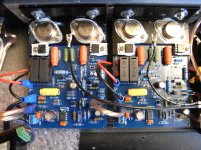
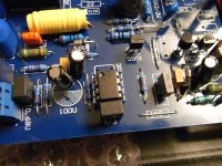
Finally managed to build the spare LJM 405 clone boards but incorporate all the recommended changes implemented and tested by Keith Snook and others. I even added a few improvements myself, using up more of the parts in the supplied assembly kits. I also found out how easy it was to use a Dremel to drill holes to fit new components and connect the legs neatly beneath the boards, very close to their connected components. The new version still has far fewer components than the original, especially since I did not fit the current-limiting circuits. Having gone to all this trouble (ok, it was fun!), I fitted Burr Brown OPA604 instead of the TL071's I had fitted to check the boards on the bench. Incidently, I initially made the mistake of using the LM301A supplied with the kit but with the compensation capacitors now removed, the boards went into oscillation 😱.
The differences between the modified and unmodified LJM 405 clone are not subtle. The difference is far more noticeable than the initial change between the original Quad 405 and the LJM clone. Finally, the harsh, horrible treble has disappeared and you can now hear real cymbals and hi-hats. All instruments sound better, more dynamic and precise. Vocals have much greater clarity and stand-out individually in the sound-stage whereas before the lead and backing vocals seemed to merge together in a kind of musical mush. This amplifier is worth keeping and could probably stand its own ground with some much more expensive "designer" amplifiers. It sounds so good, I might even consider using my pcb layout skills to make a clone of the clone 😀. Poetic justice methinks!
Attachments

If you look at this low-res image (to fit the page), you can still see that the opamp is indeed the input stage in the 405 and operates in inverting mode, which is where the problems begin, even though the LM301 has well and truly had its day. The full size schematic is available from several sources like the service manual and explanatory notes here: Quad 405 Manual - Stereo Power Amplifier - HiFi Engine
For Keith Snook's circuit analysis and masses of well researched mods see here: QUAD 405 Amplifier Information and Modification
The op-amp wont make much difference as it's only acting as a servo.
Its not a Quad in that case. Every version (Quad and Snooks Evolution series) has the opamp as the first audio stage. A true servo is an integrator based around an opamp that applies a DC correction voltage to an earlier stage in the amplifier to correct for DC offset.
Quite correct - really horrible.
By the time the 606 was introduced the op-amp was just a servo.
By the time the 606 was introduced the op-amp was just a servo.
Opamp at the input is also problematic because it provides 15dB additional gain, which together with the rest of the circuit makes 50dB gain. That's way too much for most modern preamplifiers. Therefore circuit like QUAD 606 makes more sense altogether. No opamp = no noise problem in the first place (no matter if it is inverting or non inverting mode).
Thanks for all your comments. I think the main point of the re-design exercise on the original QUAD 405 was to keep the amplifier as close to the original design as possible but remove the obvious imperfections and compromises to reveal the true sound of the amplifier. To that extent, I think it was a great success and the final sound quality was well worth the effort. Not surprisingly, the input stage op-amp was the primary cause of most of the sonic ills of this otherwise great 1970's amplifier. But the imperfect input stage Class A current source was another significant noise problem. Once corrected, you can appreciate the unique "current dumping" design in all its true glory.
Its a wrap!
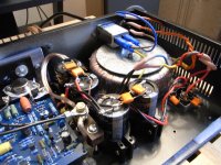
Finished off the work on my LJM 405 clone amplifier. The modules are inside the case of a defunct Samson Servo 170. I covered the front panel cut-outs with a sheet of 5mm opague acrylic. Initially, I planned to back-light with an LED or two but then I found an old ITT Cannon "crocodile-eye" mains push switch. Is this a first?. An amplifier without a power LED 🙂. I much prefer its under-stated look but in terms of sound quality, its definitely not under-stated. I recently bought a cheap Keces DA-131 Mk1.1 DAC from my favourite on-line retailer and it seems a much better sonic match for this amp than my previous Schitt Bifrost Uber, despite the big price difference. Already planning my next amplifier project. I will strip-out an old Realistic MPA-100 with cool VU meters and install a couple of high-end clone modules and beefy PSU. Its an ideal surrogate with existing caps, rectifier and huge heatsinks (not to mention the meters). Will post results in appropriate diyAudio forum.
Finished off the work on my LJM 405 clone amplifier. The modules are inside the case of a defunct Samson Servo 170. I covered the front panel cut-outs with a sheet of 5mm opague acrylic. Initially, I planned to back-light with an LED or two but then I found an old ITT Cannon "crocodile-eye" mains push switch. Is this a first?. An amplifier without a power LED 🙂. I much prefer its under-stated look but in terms of sound quality, its definitely not under-stated. I recently bought a cheap Keces DA-131 Mk1.1 DAC from my favourite on-line retailer and it seems a much better sonic match for this amp than my previous Schitt Bifrost Uber, despite the big price difference. Already planning my next amplifier project. I will strip-out an old Realistic MPA-100 with cool VU meters and install a couple of high-end clone modules and beefy PSU. Its an ideal surrogate with existing caps, rectifier and huge heatsinks (not to mention the meters). Will post results in appropriate diyAudio forum.
Attachments

- Home
- Amplifiers
- Solid State
- QUAD 405 clone