And now a size that limits to 50x25 mm to fit the plinth PCB space that holds 10kV and can be economically produced.
You have to make 24 pieces for one set of Quad ESL delay line units.
You have to make 24 pieces for one set of Quad ESL delay line units.
Depends on how much modding you want to do. I didn't like the factory SUT's and replaced with Plitron, bolted to the top of the box cover. Freed up a lot of real estate inside the box, which I used for caps.
Could you share some photos please.
Peter Walker was a transformer guru since the early forties. Yes, it had to be commercially implemented so there were limitations.
Menno van der Veen also is a transformer specialist. Different pricing.
Going from 1-120 to 1-75, 35% is a Big step IMHO.
Peter Walker was a transformer guru since the early forties. Yes, it had to be commercially implemented so there were limitations.
Menno van der Veen also is a transformer specialist. Different pricing.
Going from 1-120 to 1-75, 35% is a Big step IMHO.
I'm curious if you checked low frequency limits with the Plitrons. While their toroidal transformers tend to perform better at high frequencies than typical EI designs, when I tried to run them full-range-ish, they saturated/distorted more with bass at high levels (compared to a Tranex 2-0404 or a trio of Hammond 1609's).I didn't like the factory SUT's and replaced with Plitron
From your previous post's description, it sounds like you're running relatively low power though (40 watts or so?), so maybe you're not up against that limit.
I run 2 pairs of modern Quads, each pair crossed as Walker recommended, that is, perpendicular to each other. Think 2 x's. Doubling the number of speakers is how I get volume. That's right - 40W of pure, full complementary, push-pull, Class A sound.
I'll be servicing one soon, I'll take photos then.
I'll be servicing one soon, I'll take photos then.
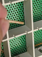
I have a question about the internal wiring, more precisely the blank, curled connections between the panels. They have a turn. The question arises then: What are these turns good for? I could not find any explanation in the net yet about this design detail.
These turn have a drawback in terms of a mechanical resonance. If you gently knock them mechanically, they nicely go doingzzzz doingzzzzz doingzzzz. I guess these resonances can also be initiated by the regular music signal. So in a first go, I damped these turns by felt, in a second one with a bead of silicone, in a third one rewiring the whole setup, making these turns now really silent. These turns now are wound around a fiberglass rod mantled by a teflon tube.


These turn have a drawback in terms of a mechanical resonance. If you gently knock them mechanically, they nicely go doingzzzz doingzzzzz doingzzzz. I guess these resonances can also be initiated by the regular music signal. So in a first go, I damped these turns by felt, in a second one with a bead of silicone, in a third one rewiring the whole setup, making these turns now really silent. These turns now are wound around a fiberglass rod mantled by a teflon tube.
That seems to be an assembly aid. Older Quads sis not have those. It will have very little effect on anything in that application. Those wires tie the various rings on the stators together.

heating PTFE above about 475 F can generate toxic gasses, including HF.
!!!
Thank you for this important warning.
The wires indeed are PTFE isolated. And, for the little and innocent side-story, as this PTFE isolation was nastily tenaciuous for my cutter and heat-resistant (up to 350°C) for my soldering iron, I looked for some alternatives to de-isolate the wire ends to solder. And after a series of rather frustrating experiments I finally was tempted to use a micro/precision gas-burner to do so ... Kind to try to "simply" burn/melt PTFE away at the ends of the wire, and then eventually clean the residuals. Most elegant, I thougt, and hoping the wire would not take some oxydation while doing so ... THIS IS A NO-GO: Fortunately I felt diffusely uncomfortable enough about this idea and made a search about PTFE and it's higher temperatures properties before lighting up the burner.
Meanwhile, I found a much better way to de-isolate the ends, without any harm, neither for the conductor, nor for the de-isolating man at the bench: Cut the wire to its length. Then selectively grab only the conductor with an appropriate, small pincer, leaving the insulation out of the grip. Then simply pull back the isolation. PTFE nicely glides on the central conductor wire. You can make it glide away for the double length of the intended de-isolation, cut the other end of the isolation away, and then make it glide back. You will have then both ends beautifully de-isolated.
Then, soldering these PTFE isolated wire at 300°C ... 350°C is/was on the safe side. No sudden death, no caughs, no heart failure, still in best condition.
Finally an erratum: These supporting 2.5mm fiber glass rods I mentionned and showed in the fotos are not manteled with a Teflon/PTFE tube, but with a Silicon tube (2mmx4mm) instead.
Not that you should necessarily do as I do, but I have a strong breeze blowing, strong fans, when I solder any where near PTFE, and try to keep the temp to 250C. And a respirator rated for HF. I'm really paranoid about that stuff, so I try not to use PTFE at all..
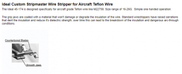
There ae stripping tools specifically for Teflon wire. They work well.
Every aspect looks to make for easier assembly, solid conductor and teflon insulation means easier to put in the right place and not burn the insulation.
I would replace those wires with silicone insulated stranded wire. e.g.: https://www.amazon.com/BNTECHGO-Sil...-Impedance/dp/B06Y2NBJJ2?ref_=ast_sto_dp&th=1 Super soft and flexible.
Yes, stranded wire is flexible - that's the problem for this application. You want something to hold its shape long enough to solder it in place. IME
I use a set of hotweezers for stripping wire, both teflon and lesser types. I come from an aerospace industry and these things are pretty common. I bought mine surplus.
https://meiseitools.com
Sheldon
https://meiseitools.com
Sheldon
I can also recommend the hot tweezers (I have a set) and Clauss no-nik's which are hard to find except on eBay and the Ideal stripmaster with Teflon blades. I have all of these and use them all depending on what I'm doing. The challenge of soldering to the Quad panels is not dripping solder into the panel. With the right tools and setup its manageable with stranded wire.
Agreed about solder in the panels. I use squares of shrink-wrap in the cells adjacent to contact points. I have two Stripmasters - but don't recall teflon blades. Could you elaborate, please?
Many thanks to the OP for this guide. My 2805 panels failed after ~15 years, and I was able to inject new life into them as shown in these photos without dismantling the guts of the speaker. They've been running well for some weeks now so I thought I'd share this method in case it helps anyone avoid more hard labor.
It turns out our $9000 speakers were held together by good ole bookbinding glue, aka polyvinyl alcohol, in other words hot stick glue from the crafts store. When I took off the dust cover there was a strong smell of "old library". Surely the extra $0.02 on the BOM for a few dabs of quality epoxy would have killed them profits. The problem with PVA is it turns brittle and cracks, especially quickly at elevated temperatures. Black speaker in the living room in sunlight, planned obsolescence if I ever seen one.
The failure mode is that the green circuit boards come undone from the hard plastic grids that keep them at the correct distance from the membrane, and some want to curl in towards the membrane, causing arcing that will eventually destroy the speaker. In my case the speakers were sitting unused in storage for a couple of years, and when I powered them up I immediately heard the arcing and shut them down. There were no obvious perforations on the membranes that I could see. Some minor perforation will most likely have no audible effect; I'm not sure at what level of damage would one decide to rebuild the whole thing.
What I did was:
Find some weather striping with strong self-adhesive tape and a hollow profile into which a paper clip can be inserted.
Very gently tack a short strip of the weather striping onto the circuit boards near the corners where they curl in toward the membranes. Bend a paper clip so it can be used to pull onto the weather striping. The idea is to pull the circuit board back out toward the plastic grid while applying a dab of hot glue to hold it in place temporarily. Once the hot glue has cooled pull off the weather striping. Repeat this at every corner where the circuit board has separated from the grid.
Once all of the circuit board is at its correct distance, touching the plastic grid, mix up a batch of slow epoxy and use a toothpick to place a tiny dab at most corners of the grid--especially the ones on the periphery. Let the epoxy cure for > 24 h before putting any stress on it, and surely it will outlive most of us.
YMMV and all that; for me this was well worth the effort so far.
Attachments

In this way, as it is done by some/several/many repair companies and DIY persons, you have no control over, and no way to check how even the stator is glued to the grid because of the old glue remaining, no matter how hard you pull.
This means there can/will be differences in distance between stator and diaphragm over the surface.
Please don't say you can see it is even, because we are talking maximum of 0,2 mm difference allowed. You can't see that wit the naked eye.
No idea where all that temporary hot melt glue goes through the mesh?
It is a painstaking job that has to be repeated for x ribs on 16 or 24 grid panels sides,
One slip of the paperclip on the non mesh side (if you don't open up the panels) and you perforate the Mylar.
So as you might expect, prefer to take apart the stator completely, clean it thoroughly and start from scratch with new glue and new Mylar.
What glue can be applied simple evenly on those very narrow ribs?
What is the open time of the glue?
How does the glue bond? Does it need pressure / UV / high temperatures applied?
What is the drying time complete dry? 24 hours? 48 hours?
It has to be made in serial production, not just 1 set over days or weeks.
No easy task, not easy at all, even when cost is no object.
This means there can/will be differences in distance between stator and diaphragm over the surface.
Please don't say you can see it is even, because we are talking maximum of 0,2 mm difference allowed. You can't see that wit the naked eye.
No idea where all that temporary hot melt glue goes through the mesh?
It is a painstaking job that has to be repeated for x ribs on 16 or 24 grid panels sides,
One slip of the paperclip on the non mesh side (if you don't open up the panels) and you perforate the Mylar.
So as you might expect, prefer to take apart the stator completely, clean it thoroughly and start from scratch with new glue and new Mylar.
I also think there is much much more to it.It turns out our $9000 speakers were held together by good ole bookbinding glue, aka polyvinyl alcohol, in other words hot stick glue from the crafts store. When I took off the dust cover there was a strong smell of "old library". Surely the extra $0.02 on the BOM for a few dabs of quality epoxy would have killed them profits.
What glue can be applied simple evenly on those very narrow ribs?
What is the open time of the glue?
How does the glue bond? Does it need pressure / UV / high temperatures applied?
What is the drying time complete dry? 24 hours? 48 hours?
It has to be made in serial production, not just 1 set over days or weeks.
No easy task, not easy at all, even when cost is no object.
Right; to be clear, the choice for me was between throwing them in the trash vs. perhaps getting a few more years of precarious auditory bliss. Doing a complete rebuild is simply not worth my time. I did try contacting a couple of folks on the West coast who used to do this, nobody will touch Quads anymore as it's not worth the effort.
I understand that some folk seek perfection in every solder and wire, but regarding the 0.2 mm tolerance keep in mind you're twisting the entire panel by half an inch with that rear brace. No way 0.2 mm on anything will make any kind of objective difference in the sound. The manual for a pair of Martin-Logans I used to own clearly stated that an occasional visible membrane puncture is nothing to worry about, and to vacuum the panels every couple of weeks.
P.S. Removing the "dust covers" did seem to get rid of a particular plasticky slam sound during sharp transients that I've come to associate with electrostats. Go figure...
- Home
- Loudspeakers
- Planars & Exotics
- QUAD 2805/2905 dismantling: in pictures (part 2)