Hi, I have a question about changing the EQ bypass enable/disable parameter.
I have two of Wuzhi Audio's QCC5125 & PCM5125 BT receiver boards sold here:
https://id.aliexpress.com/item/1005006238395176.html
To change the EQ setting for my speakers, I followed the steps shown in the tutorial "How to change the QCC303x series Bluetooth EQ settings" on the TinySine website:
https://www.tinysineaudio.com/blogs/news/how-to-change-the-qcc30xx-series-bluetooth-eq-settings
I got no issues from the beginning through step 3 in "3. Save QCC30xx series Bluetooth EQ settings."
I successfully changed the EQ setting on the QACT tool and then saved the parameters using QCC_Audio_Tool.
However, the ADK_Configuration tool cannot connect to the board by USB.
The EQ setting changed the sound on the QACT tool in the monitoring mode (Full), but when resetting the board after writing the parameters on QCC_Audio_Tool, the EQ setting was not working, and the QACT tool read the parameters that I had written with QCC_Audio_Tool.
How can I get the ADK Configuration tool connected to the board and configure the parameter?
Maybe I need the same version of the ADK tool used for the development of this board, but so far I haven't got any info.
Is there a config xml file for this board? or should I need an SPI connection? any help is welcome.
Alternatively, is there any other means of disabling the EQ bypass parameter on the firmware?
Thank you very much!
FYI, All tool versions are the same as shown on the tutorial webpage.
Attachments
I have a problem with the QCC5125, which is causing it to fail with AHI_ERROR_INVALID_MESSAGE (ADK Config App) which always gets stopped at block 1398.
It is supposed to be compatible with QCC3031 as well as 5125, so I'm not sure what's going on. (ADK 6.4.2.26_QCC3031_QCC5125)
Also here's a summary of the method I used to connect to the board:
It is supposed to be compatible with QCC3031 as well as 5125, so I'm not sure what's going on. (ADK 6.4.2.26_QCC3031_QCC5125)
Also here's a summary of the method I used to connect to the board:
- Find USB_DP, USB_DN, VBUS and GND
- Using a cut USB cable, connect to the pins (leave the battery off) and connect to your PC
- Install BlueSuite 3.3.10 + ADK 6.4.2.26
- See the device manager and find "Qualcomm USB Hub - XXXX" where "XXXX" is a 4-digit number
- Find a device with the hardware ID of VID 0x0A12 and PID 0x4010 (for QCC5125)
- Update the driver from BlueSuite's driver folder (Select "UsbDebug.inf")
- Go to the QTIL folder where BlueSuite is installed
- Make a text file "key.txt" with this written inside: 00000000000000000000000000000000
- Put the text file inside the QTIL folder where TransportUnlock.exe is
- Using the admin command prompt, execute "transportunlock writeunlockkey key.txt" (without quotes)
- If all is good, it should end with "Success"
- Immediately go to the start menu and find NvsApp
- Connect to the device and select "Dump" from the operations list
- Make a dump of the device
- Read device, make changes, write device, then always read it back
- If settings or firmware is damaged and the device is malfunctioning, use NvsApp to write the backup you made back onto the device
@German1212
I know this was an old post, but would like to ask if QCC3024 IC form qualcomm needs speacial programming when you change the IC itself?
I have a helmet bluetooth intercom using the QCC3024 IC, unfortunately got burned due to over charging. Can I just replace the QCC3024 IC and the intercom will work again? Or it needs some sort of programming for it to work?
Thanks in advance.
Not sure if this is possible but I've been trying to generate custom tones for the QCC3031. I'm connected via USB debug. I'm also unable to connect to QACT but I'm not really worried about that. This is for a TSA8804 although I had better luck burning the firmware for the TSA6179 as part of the requirements is to have multiple devices connected (party mode) and the firmware for the TSA8804 doesn't allow this. Right now I am happy with almost everything but it would be super cool to have some custom sounds when the amp turns on.
I am about to generate and it shows a message box with the message:


I am about to generate and it shows a message box with the message:
Halo can anyone help me so that this module can use the tws feature, I have tried to change it but I didn't find anything in the old programming software, there is no tws feature, is there anyone who can help me so that this module can support the tws feature of the qc5125 module, thank you
Attachments

Hello sir, can I request the dump file for QCC5125 module. I programmed it wrong and now it can't connect to the cellphone, but it can still detect the USB port on the PC.Hi all!
I have had quite a lot of experience with portable speaker design and Bluetooth modules from Qualcomm. I worked with CSR chips, for example, CSR64215 and I didn’t get any problem with programming this chip. Moreover, we have a great thread on this forum with a lot of useful information: CSR8675 programming guide w. software and tons of CSR info
On the market, we have new Qualcomm chips QCCXXXX and the approach of programming not the same with CSR modules. As far as I know, the last chip that supports CSR programming process is QCC3008.
And new chips have features:
- APTX-HD, APTX-Adaptive (QCC5125)
- DSP Kalimba, a key feature for me.
- Bluetooth 5.1
- Ready-made modules with amplifiers and external DACs
These chips have DSP Kalimba and that gives the opportunity to set up audio how I want, make limiter, EQ, bass booster, etc.
I know that this DSP not so powerful as, for example, ADAU1701, but that makes my project chipper using only one chip for wireless connection, DAC and DSP.
QCC5125 and QCC3034\QCC3031 have the same programming approach. For programming those modules, we have two ways. First, we need special programming expensive board. Second, programming with USB.
I found ADK for QCC3031 on the thread that I write above, thanks a lot @ErikDIY for that. I tried to connect this chip to a USB, but I didn’t get any success.
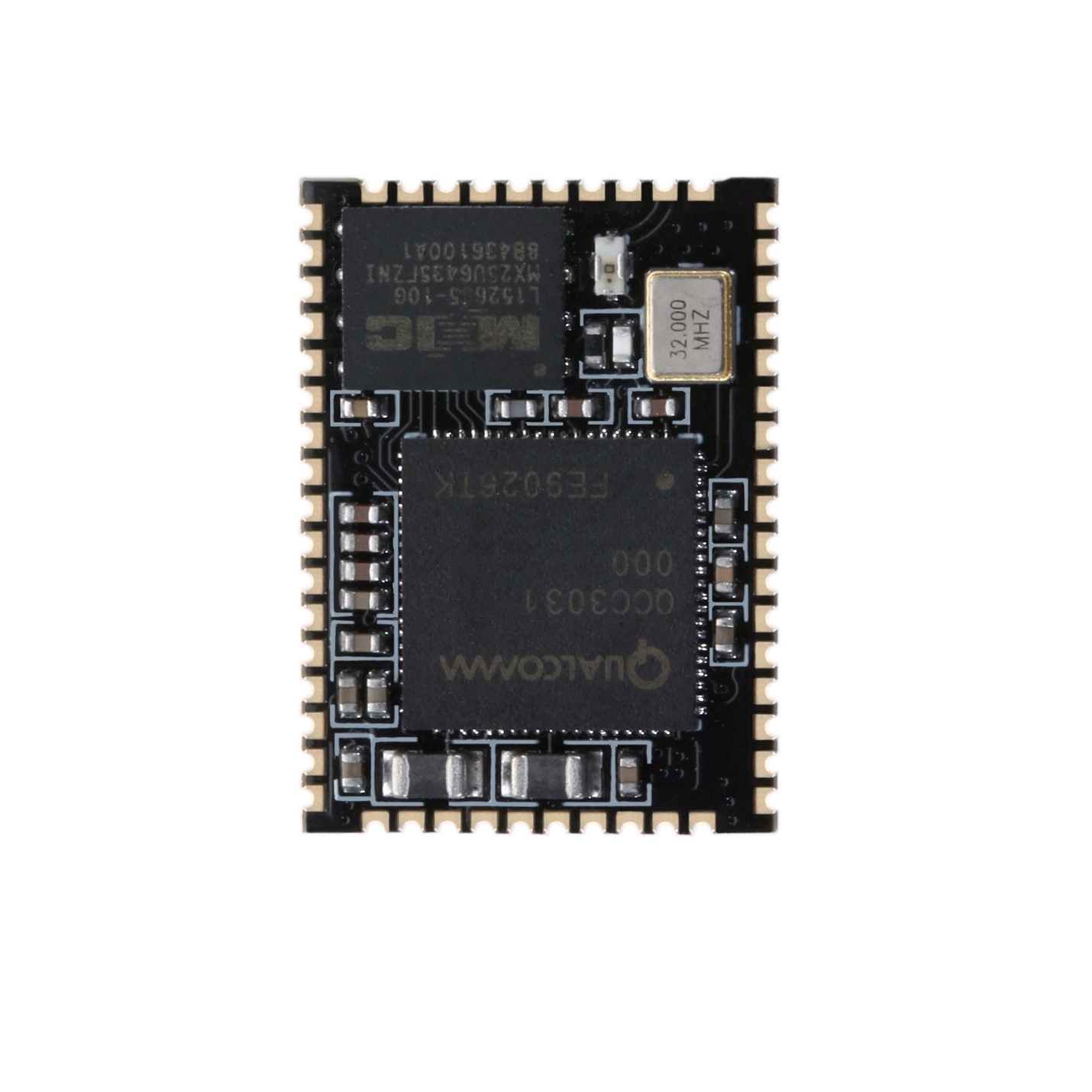
I have this module - BTM331.
I would like to ask you to share your experience, how connect this chip to USB? How configure DSP Kalimba on this chip by USB?
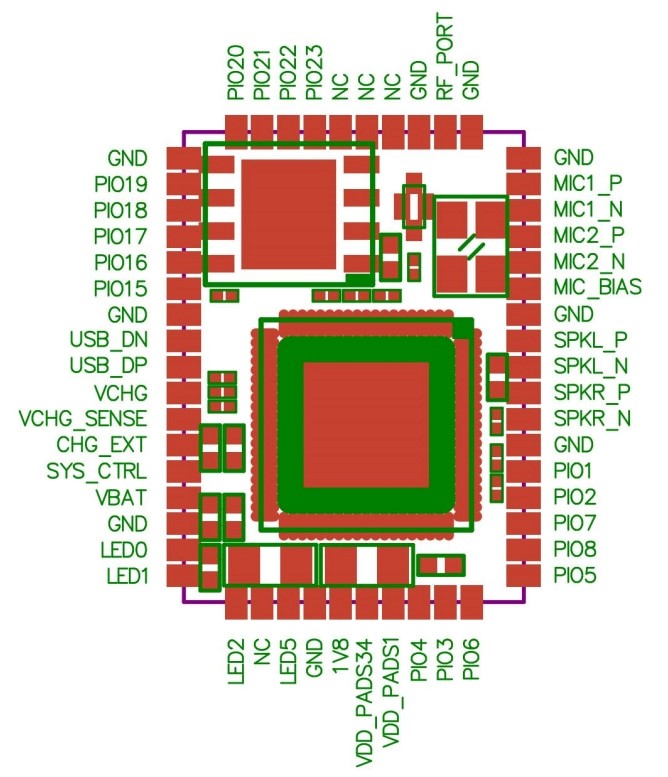
On USB we have 4 pins
- GND,
- Data+
- Data-
- +5V
And we have pins on QCC3031(BTM331):
- VBAT_SENSE
- USB_DN
- USB_DP
- VCHG
- VCHG_SENSE
- CHG_EXT
Which pins from qcc3031 I need to connect to USB pins?
As I understood Data+ and Data- from USB need to connect to USB_DN, USB_DP from QCC3031.
Hello, have you got the file? I also really need that fileHello,
Can someone please share xuv file of original qcc5125 chip with APTX-HD and without Ldac.
The problem is that my BT module is ldac enabled and Android smartphone uses Ldac as preferable by default. It generates 96khz stream which is not compatible with my DSP.
Thanks.
Hello, can you help me? Can you send me that firmware file? My module is brokenHi all, I have updates about configuring QCC3034, and let me share those with you guys.
First many thanks to @hvmcsa, he shared with me qcc_tool where I can change the name of the chip.
Second, about backup. I understood how backup original firmware. You need to use NvsApp.exe in BlueSuite. And it works. I backed up the original firmware with this tool, broke my chip after MDE deployment, and successfully restored it from backup. Rule #1 before any changes do backup!
Third, about Kalimba DSP. You can config DSP with the QACT tool. Need to enable chip, connect to it with Bluetooth and USB, and run some audio, that gives you enable online configuration. But I have some problem with that, I can't save config on my chip. After rebooting the chip all settings became the default. And I don't know how to fix that.
How save DSP settings on the chip after reboot?
Could somebody help me with the correct orders and steps to save DSP config?
Thanks.
Hi,
I am now able to configure qcc3031/34 modules so that the xover DSP module is activated and used. For that I have to configure three or four output channels, double stereo or stereo+sub.

To do that I have to configure I2S and DAC output together although I am only using the DAC outputs:


Unfortunately that leads to sporadic distortions (on DAC outputs). Sound is perfectly fine but has bad distortions (sounds digital) every 30 seconds or so.
If I configure only DAC or only I2C there are no distortions ever:

It seems like they only occur if DAC and I2C are outputs are used together, even with only two outputs configured (primary left->DAC left, primary right->I2C right):

DSP still has 20-30% free, doesn't seem to be the bottleneck.
I2S pins are not connected on the module and floating.
Has anyone experienced something similar?
Or has anyone used I2C and DAC outputs together without issues?
I have been doing exactly this with QCC3008 for quite some time now without any problems.
I am now able to configure qcc3031/34 modules so that the xover DSP module is activated and used. For that I have to configure three or four output channels, double stereo or stereo+sub.
To do that I have to configure I2S and DAC output together although I am only using the DAC outputs:
Unfortunately that leads to sporadic distortions (on DAC outputs). Sound is perfectly fine but has bad distortions (sounds digital) every 30 seconds or so.
If I configure only DAC or only I2C there are no distortions ever:
It seems like they only occur if DAC and I2C are outputs are used together, even with only two outputs configured (primary left->DAC left, primary right->I2C right):
DSP still has 20-30% free, doesn't seem to be the bottleneck.
I2S pins are not connected on the module and floating.
Has anyone experienced something similar?
Or has anyone used I2C and DAC outputs together without issues?
I have been doing exactly this with QCC3008 for quite some time now without any problems.
Last edited:
Hi guys!
Some time ago I played with CSRA64215 and QCC3005 modules, finding the software and their correct versions was a bit messy but no terrible.
Now I got a BTM334 QCC3034 module and I'm having plenty of issues.
So far:
- I unlocked the module,
- Only ConfigApp from BlueSuite 3.3.18 worked properly, I downloaded from here: https://disk.yandex.ru/d/vB-9qaWN74XXIQ/qcc5181
I can change the device name there without bricking the module.
Older versions like 3.3.3 only recognized few keys and bricked the module when writing.
- NvsApp works, I can write and read the flash just fine:

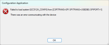
- ADK Configuration Tool from ADK_QCC512X_QCC302X_WIN_6.4.2.26 also detects the module, but fails when loading the definitions:
This is a real bummer as I wanted to modify the leds /buttons behavior.

- I downloaded MDE WIN 2.3.2.126, I can build the QCC3034 Sink app...
However this module has a 32Mbit flash and the project comes with 64Mb by default.
When changing the flash config to 32Mbit the firmware deploy fails because it doesn't fit in the flash partitions.
I've removed almost everything from the options, still not fitting.

Under project config, I set STRIP_SYMBOLS to TRUE and BUILD_CONFIG to RELEASE.
I modified apps\applications\sink\32Mbit_Default_flash_config.py like this, now everything fitted.
But, this doesn't work at all, the module dies and I have to restore it with NvsApp...
However, leaving the default 64Mbit config does work!
I can't really understand why, the flash chip has a very clear marking, "25U3235" (32Mbit)!
Did anyone got ADK Tool to work?
About the FW sources, there's any API/ FW docs I can read to undertsand how everything works?
It would be great if I could inteface the module with a MCU using a serial port...
Cheers!
Some time ago I played with CSRA64215 and QCC3005 modules, finding the software and their correct versions was a bit messy but no terrible.
Now I got a BTM334 QCC3034 module and I'm having plenty of issues.
So far:
- I unlocked the module,
- Only ConfigApp from BlueSuite 3.3.18 worked properly, I downloaded from here: https://disk.yandex.ru/d/vB-9qaWN74XXIQ/qcc5181
I can change the device name there without bricking the module.
Older versions like 3.3.3 only recognized few keys and bricked the module when writing.
- NvsApp works, I can write and read the flash just fine:
- ADK Configuration Tool from ADK_QCC512X_QCC302X_WIN_6.4.2.26 also detects the module, but fails when loading the definitions:
This is a real bummer as I wanted to modify the leds /buttons behavior.
- I downloaded MDE WIN 2.3.2.126, I can build the QCC3034 Sink app...
However this module has a 32Mbit flash and the project comes with 64Mb by default.
When changing the flash config to 32Mbit the firmware deploy fails because it doesn't fit in the flash partitions.
I've removed almost everything from the options, still not fitting.
Under project config, I set STRIP_SYMBOLS to TRUE and BUILD_CONFIG to RELEASE.
I modified apps\applications\sink\32Mbit_Default_flash_config.py like this, now everything fitted.
{
"flash_device": {
"block_size": 64 * 1024,
"boot_block_size": None,
"alt_image_offset": 32 * 64 * 1024
},
"encrypt": False,
"layout": [
("curator_fs", { "capacity" : 1 * 64 * 1024, "authenticate": False, "src_file_signed": False}),
("apps_p0", { "capacity" : 9 * 64 * 1024, "authenticate": True, "src_file_signed": True}),
("apps_p1", { "capacity" : 7 * 64 * 1024, "authenticate": False}),
# Device config filesystem size limited by size of production test buffer, ( 1024*2)-10.
("device_ro_fs", { "capacity" : 1 * 64 * 1024, "authenticate": False, "inline_auth_hash": True }),
("rw_config", { "capacity" : 1 * 64 * 1024}),
("rw_fs", { "capacity" : 1 * 64 * 1024}),
("ro_cfg_fs", { "capacity" : 2 * 64 * 1024, "authenticate": False}),
("ro_fs", { "capacity" : 10 * 64 * 1024, "authenticate": False})
]
}
But, this doesn't work at all, the module dies and I have to restore it with NvsApp...
However, leaving the default 64Mbit config does work!
I can't really understand why, the flash chip has a very clear marking, "25U3235" (32Mbit)!
Did anyone got ADK Tool to work?
About the FW sources, there's any API/ FW docs I can read to undertsand how everything works?
It would be great if I could inteface the module with a MCU using a serial port...
Cheers!
Attachments

More findings:
Device Name and MAC address can be edited in dev_cfg_filesystem/common/subsys1_config2.htf
I2S won't work by default, needs to be enabled in fw_cfg_filesystem/subsys3_config1.htf
Without this, the I2S config will be missing in ADK Tool.
Comment these lines for I2S1 (Pcm) / I2S2 (Pcm1):
Got it working after swapping the flash with a 64Mbit one, but this was far from optimal.
I kept tweaking the partitions, got it working on 32Mbit with this config:
(apps\applications\sink\32Mbit_Default_flash_config.py):
Device Name and MAC address can be edited in dev_cfg_filesystem/common/subsys1_config2.htf
I2S won't work by default, needs to be enabled in fw_cfg_filesystem/subsys3_config1.htf
Without this, the I2S config will be missing in ADK Tool.
Comment these lines for I2S1 (Pcm) / I2S2 (Pcm1):
Code:
#PcmPioConfig =  [ 10 11 ff 12 13 ]
#Pcm1PioConfig = [ ff ff ff 14 16 ]
Got it working after swapping the flash with a 64Mbit one, but this was far from optimal.
I kept tweaking the partitions, got it working on 32Mbit with this config:
(apps\applications\sink\32Mbit_Default_flash_config.py):
Code:
{
    "flash_device": {
    "block_size": 64 * 1024,
    "boot_block_size": None,
    "alt_image_offset": 32 * 64 * 1024
},
"encrypt": False,
"layout": [
    ("curator_fs",      { "capacity" :  1 * 64 * 1024,  "authenticate": False, "src_file_signed": False}),
    ("apps_p0",         { "capacity" : 9 * 64 * 1024,  "authenticate": True, "src_file_signed": True}),
    ("apps_p1",         { "capacity" :  8 * 64 * 1024,  "authenticate": False}),
    # Device config filesystem size limited by size of production test buffer,  ( 1024*2)-10.
    ("device_ro_fs",    { "capacity" :  1 * 64 * 1024,  "authenticate": False, "inline_auth_hash": True }),
    ("rw_config",       { "capacity" :  1 * 64 * 1024}),
    ("rw_fs",           { "capacity" :  1 * 64 * 1024}),
    ("ro_cfg_fs",       { "capacity" :  2 * 64 * 1024,  "authenticate": False}),
    ("ro_fs",           { "capacity" :  9 * 64 * 1024,  "authenticate": False})
]
}
Last edited:
Update: It's been impossible to use ADK with 32Mbit flash.
The partition hacks above made it to compile and work, but ADK crashed when connecting.
Updated to 64Mbit flash, everything works.
I simply replaced the flash, the debug interface still worked, I could upload the new fw without major issues.
It seems to me they cheapened on the modules, as all the pictures show a 64Mbit flash, but you get 32!
I'll buy these: www.aliexpress.com/item/1005001412682635.html
Note that it must be 1.8V flash! (W25Q64JW) W25Q64JV is 3.3V-only!
There was a bug in Gaia EQ, the settings were gone after powering the module off.
I found the solution here: https://www.52bluetooth.com/thread-84921-1-5.html
I'm posting the code here just in case, but it didn't work!
sink_audio_routing.c
sink_a2dp.c
The partition hacks above made it to compile and work, but ADK crashed when connecting.
Updated to 64Mbit flash, everything works.
I simply replaced the flash, the debug interface still worked, I could upload the new fw without major issues.
It seems to me they cheapened on the modules, as all the pictures show a 64Mbit flash, but you get 32!
I'll buy these: www.aliexpress.com/item/1005001412682635.html
Note that it must be 1.8V flash! (W25Q64JW) W25Q64JV is 3.3V-only!
There was a bug in Gaia EQ, the settings were gone after powering the module off.
I found the solution here: https://www.52bluetooth.com/thread-84921-1-5.html
I'm posting the code here just in case, but it didn't work!
sink_audio_routing.c
Code:
static bool audioRouteSource(audio_sources source)
{
    bool routing_success = FALSE;

    if(isAudioRoutingPermitted(source))
    {
        switch (source)
        {
            case audio_source_FM:
                routing_success = audioRouteFMIfAvailable();
                break;

            case audio_source_ANALOG:
                routing_success = audioRouteAnalogIfAvailable();
                break;

            case audio_source_SPDIF:
                routing_success = audioRouteSpdifIfAvailable();
                break;

            case audio_source_I2S:
                routing_success = audioRouteI2SIfAvailable();
                break;

            case audio_source_USB:
                routing_success = audioRouteUsbIfAvailable();
                break;

            case audio_source_a2dp_1:
            case audio_source_a2dp_2:
                routing_success = audioRouteA2dpIfAvailable(source);
                break;

            case audio_source_ba:
                routing_success = audioRouteBaIfAvailable();
                break;

            case audio_source_none:
            default:
                break;
        }
        AUD_DEBUG(("AUD: audioRouteSource source = %d routed = %d\n", source, routing_success));
    }

    if(routing_success) //这里是添加的
        MessageSendLater(&theSink.task, AUDIO_DSP_READY_FOR_DATA, 0, 0);

    /* Disconnect any currently routed sources in case requested source didn't make it.*/
    if ((routing_success == FALSE) && (sinkAudioIsAudioRouted()))
    {
        AUD_DEBUG(("AUD: Nothing to route, disconnecting\n"));
        audioSuspendDisconnectAudioSource();
        updateVolumeBasedOnRoutedSources();
    }

    displayUpdateAudioSourceText(sinkAudioGetRoutedAudioSource());

    /* indicate whether audio was successfully routed or not */
    return routing_success;
}
sink_a2dp.c
Code:
void handleA2DPUserEqBankUpdate(void)
{
user_eq_bank_t *PEQ = NULL;
PEQ = sinkAudioGetPEQ();
//if(PEQ && (PEQ->bands[0].Q != 0))
if(PEQ) //修改这里
{
uint16 index = 0;
eq_param_type_t param_type = 0;
audio_plugin_user_eq_param_t param;
param.id.bank = 1;
param.id.band = 0;
param.id.param_type = 0;
param.value = MAX_EQ_BANDS; /* Number of Banks */
AudioSetUserEqParameter(sinkAudioGetRoutedAudioTask(), ¶m);
param.id.param_type = 1;
param.value = PEQ->preGain; /* Master Gain */
AudioSetUserEqParameter(sinkAudioGetRoutedAudioTask(), ¶m);
for(index = 0; index < MAX_EQ_BANDS; index++)
{
param.id.bank = 1;
param.id.band = index + 1;
for (param_type = 0; param_type < eq_param_max_param_types; param_type++)
{
param.id.param_type = param_type;
switch (param_type)
{
case eq_param_type_filter:
param.value = PEQ->bands[index].filter;
break;
case eq_param_type_cutoff_freq:
param.value = PEQ->bands[index].freq;
break;
case eq_param_type_gain:
param.value = PEQ->bands[index].gain;
break;
case eq_param_type_q:
param.value = PEQ->bands[index].Q;
break;
default:
break;
}
AudioSetUserEqParameter(sinkAudioGetRoutedAudioTask(), ¶m);
}
AudioApplyUserEqParameters(sinkAudioGetRoutedAudioTask(), TRUE); //修改这里
}
}
}
Last edited:
Shame to have an audio suite and android apps for a BT device, but being unable to do anything via bluetooth. I had mistakenly thought bluesuite would do just this, but alas, I'm not seeing this functionality. Which would be great for people buying these modules, with no desire to start soldering them to their PC just to change it's name, or such. Even an end user can't keep track of all the BT names being broadcast around their homes, and would really benefit from naming them.
I see this is an old device now, not meant for new projects. I can only keep my fingers crossed, that they recognise this common need.
Or, did I miss something? Perhaps the new one (which must be out) or a BT app exists?
Edit: These don't sound half bad though. I'm using one right now.
I see this is an old device now, not meant for new projects. I can only keep my fingers crossed, that they recognise this common need.
Or, did I miss something? Perhaps the new one (which must be out) or a BT app exists?
Edit: These don't sound half bad though. I'm using one right now.
Try this, though it didn't work for me!Or, did I miss something? Perhaps the new one (which must be out) or a BT app exists?
If you want to try to change the name and play around with the audio presets/filters on QCC chips, here's an Android app that I got from an Ali seller with my QCC3034 boards.

Oh wow, I like that post in the past, but windows machine, not on app store, qualcomm descriptions.. looked bad. I'm connected though! Countdown to firmware request has began lol Nice!
If only I could work it..
More to follow..

Opening page, and the page that opened. It looks right, but I'm more nervous than a first date
If only I could work it..
More to follow..
Opening page, and the page that opened. It looks right, but I'm more nervous than a first date
Last edited:
So I wrote in ROKSAN (as it's going in a Roksan) and pressed the set name button. Back page. Same name. Forward page, reboot effect button. Back page. Disconnected. Wouldn't reconnect. Cycled power and app, connects again. Phew! but the Roksan name only appears on that second page, in the middle, where it says Dev name/*#@<10.. it now says ROKSAN underneath. So this looks like a naming scheme for the app, when you have many devices to tell apart. Not to give the device a new name to broadcast
The audio section looks okay. Filters and stuff. Not dug in yet

The audio section looks okay. Filters and stuff. Not dug in yet
Last edited:
The CSRA64215 was simple to work with, also did the QCC3005...
But for the love of God, these new modules, firmwares and tools are utter crap!
ADK crashes every then and now, ocassionally screwing the module or writing nothing and losing your work.
The provided QCC3034 sink firmware has infinite bugs, not only I can't store gaia EQ, but the buttons don't work properly either.
The only working input method is Rising and Falling, any other (Short, SH single, Long...) does nothing!
Do you recommend any other module that's readily available, not crazy expensive, works properly with ADK out of the box and supports I2S master output and APTX?
Sorry to hear of your problems. I can't offer any advice though. I'm just the guy that bought a module ( https://www.aliexpress.com/item/1005002723018618.html ) to get BT into an old amp. It's still managing to bug me though. This board has a relay, which defaults to analogue throughput if there is no BT. If I had the I2S connection, I could swap L&R which it has backwards, and make BT default. Instead, I have to listen to it clicking away, every time my phone gets the idea I might use use it, so it must check the connection. Literally, I unlock my phone, and it's Click, Click. Open a browser. Click Click. Start typing, Click..until I finish, then Click. How can such a small relay be so loud! It needs it's own damping project.
This 3034 isn't for new designs they say, but they may carry on the series I guess. Something must be current, if they say it's not this one.
edit: I did try the purple update button, but it seemed a redundant feature.
This 3034 isn't for new designs they say, but they may carry on the series I guess. Something must be current, if they say it's not this one.
edit: I did try the purple update button, but it seemed a redundant feature.
Hi again!
I made a small board, I think I did everything in the same way as I had in the wired prototype, but clearly I missed something out.
The module doesn't start when VDD_PADS are connected to any power. I tried both 1v8 and 3v3.
I recall having these pins connected to 3V3, VBAT and VBAT_SENSE as well.
If I connect the module with to the USB and issue a reset with NvsApp, the module starts working.
If I leave these pads floating, it also boots properly.
I use a MCU to control the module, SYSCTRL pin is tied to ground and delayed for 2 seconds, then set to 3.3V to start the module.
In that moment the module enables the 1V8 regulator and it should work... but it doesn't.
I'm sure this approach worked well before!
What I could I be doing wrong? Thanks!!
- Home
- Source & Line
- Digital Line Level
- QCC5125 and QCC3034\QCC3031 programming