Hello,
I have the pleasure to present you a new PCB design developed in cooperation with @Moor.
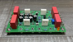
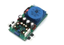
The "Sigma22 is a high-performance DIY dual-rail, tracking, linear regulated power supply.
The Q17-SIGMA-PSU power supply is inspired by Ti Kan's Sigma22 circuit.
This power supply provides a regulated up to 60vDC and 3A continuous source (with external heatsinks). The voltage difference between output and input is around 6V.
The challenge was to make it a power supply capable of working with amplifier boards. This will make it possible to overcome the fluctuations of the mains which nowadays range from 220V to 250V in our Europeans regions. While having outstanding technical characteristics (high bandwidth, instantaneous current limited by the transformer and the diodes, low noise (uV level and high PSRR)). Everything a switching power supply doesn't have.
Compared to the original design, the precision has been improved through the use of a circuit based on TL431B, a new servo motor based on an H-Bridge ZHB6792 chip from Diodes Incorporated, the addition of a trimmer to adjust the voltage and better protection in the event of failure. All in 75x130mm.
I chose to only deal with the regulation part of the PSU. This leaves you free to choose the appropriate filter board and sized according to the needs of the amplifier board.
More on the board here on my GitHub repository.
Regards,
Stef.
Version [1.1.1] (5-05-2024)
I have the pleasure to present you a new PCB design developed in cooperation with @Moor.
The "Sigma22 is a high-performance DIY dual-rail, tracking, linear regulated power supply.
The Q17-SIGMA-PSU power supply is inspired by Ti Kan's Sigma22 circuit.
This power supply provides a regulated up to 60vDC and 3A continuous source (with external heatsinks). The voltage difference between output and input is around 6V.
The challenge was to make it a power supply capable of working with amplifier boards. This will make it possible to overcome the fluctuations of the mains which nowadays range from 220V to 250V in our Europeans regions. While having outstanding technical characteristics (high bandwidth, instantaneous current limited by the transformer and the diodes, low noise (uV level and high PSRR)). Everything a switching power supply doesn't have.
Compared to the original design, the precision has been improved through the use of a circuit based on TL431B, a new servo motor based on an H-Bridge ZHB6792 chip from Diodes Incorporated, the addition of a trimmer to adjust the voltage and better protection in the event of failure. All in 75x130mm.
I chose to only deal with the regulation part of the PSU. This leaves you free to choose the appropriate filter board and sized according to the needs of the amplifier board.
More on the board here on my GitHub repository.
Regards,
Stef.
Version [1.1.1] (5-05-2024)
- Q2 orientation corrected.
- Modified TR1 footprint.
- Modified symbol for CRD E-502 and E-562.
- Replaced C5, C6, C7 and C8 with 220uF 80V (for 3A use)
- Uploaded LTSpice model.
- Uploaded Kicad and Gerber files.
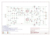
- Update diagram with real voltage measures.
- Modified U1 and U2 footprint (SOT-223-8).
- Moved C12, C13, C14, C15 and R5.
- Enlarged some tracks.
- Initial release.
Attachments

Last edited:

Technical features as described :
1. Ultra-low noise (μV level), high PSRR due to the use of TL431B 0,4%
2. Current output only limited by the mosfets Rds on
3. Input voltage only limited by the BC series transistors and the quad ZHB6792
4. Ultra-high bandwidth, limited only by the mosfets characteristics
5. The output voltage of S22 is adjustable, which is mainly determined by the chosen voltage for the Zener diode TL431, tipycal 15V up to 18V in order to got the desired output. R4//R44 has been chosen for 18V working zenner voltage. R4 alone is giving about 15V working zenner voltage and less output voltage can be adjusted. The 10K (or 20, 50 k) trimer is making a very fine tunning of the output voltage.
6. Automatic adjusting of positive and negative voltages, no matter the impedance of the load. The positive and negative voltage error is less than 3%.
7. Minimum voltage difference after rectification of the Sigma 22 output voltage should be 6V. Higher might be better but increases the power mosfet dissipation too much.
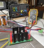
8. Initial Sigma 22 voltage drop on a continous load, has been projected at 15 uV at 12V output and 1 Amp. Five times of these settings will make larger dropout voltage but during power spikes, mainly on low bass frequencies, a very good high quality capacitors can compensate, offering current peaks of power, sufficiently enough in order to prevent large ripple voltages. Usually, without Sigma 22, voltage dropout is 5V when the signal power is rising suddenly from 0 to 100W and 9V when the power spikes got toward 200W. Well, the tests showed under continous load of 4,13A a dropout voltage of 1,1-1,2V, at 2,3 A a dropout voltage of 0,1V and at 1,47A a dropout voltage of less then 10 mV (difficult to actually measure). Sigma 22 offer a 10 times lower dropout voltage at 222W per rail, or 444W total power dual rail of a mono Q17 Mini 2.0 circuit.
I thank you Stef for projecting the miniaturised PCB ! Great work. Soon, after receiving my PCB's I'll make some photos.
1. Ultra-low noise (μV level), high PSRR due to the use of TL431B 0,4%
2. Current output only limited by the mosfets Rds on
3. Input voltage only limited by the BC series transistors and the quad ZHB6792
4. Ultra-high bandwidth, limited only by the mosfets characteristics
5. The output voltage of S22 is adjustable, which is mainly determined by the chosen voltage for the Zener diode TL431, tipycal 15V up to 18V in order to got the desired output. R4//R44 has been chosen for 18V working zenner voltage. R4 alone is giving about 15V working zenner voltage and less output voltage can be adjusted. The 10K (or 20, 50 k) trimer is making a very fine tunning of the output voltage.
6. Automatic adjusting of positive and negative voltages, no matter the impedance of the load. The positive and negative voltage error is less than 3%.
7. Minimum voltage difference after rectification of the Sigma 22 output voltage should be 6V. Higher might be better but increases the power mosfet dissipation too much.
8. Initial Sigma 22 voltage drop on a continous load, has been projected at 15 uV at 12V output and 1 Amp. Five times of these settings will make larger dropout voltage but during power spikes, mainly on low bass frequencies, a very good high quality capacitors can compensate, offering current peaks of power, sufficiently enough in order to prevent large ripple voltages. Usually, without Sigma 22, voltage dropout is 5V when the signal power is rising suddenly from 0 to 100W and 9V when the power spikes got toward 200W. Well, the tests showed under continous load of 4,13A a dropout voltage of 1,1-1,2V, at 2,3 A a dropout voltage of 0,1V and at 1,47A a dropout voltage of less then 10 mV (difficult to actually measure). Sigma 22 offer a 10 times lower dropout voltage at 222W per rail, or 444W total power dual rail of a mono Q17 Mini 2.0 circuit.
I thank you Stef for projecting the miniaturised PCB ! Great work. Soon, after receiving my PCB's I'll make some photos.
Can this be used with amps +/-36Vdc rails and Iq 1.7A class A amps also? What would be the regulator output impedance mOhm?
Actually, after a lot of digging for all sorts of power supply schematics, I tend to believe that this schematic, is among the best Linear Power Supplies available at the present time, and with a wide range of voltages and amps, just by simply changing a resistor. It is better then even Beatechnik 's Everesolo LPS-A6, or the Teddy Pardo's version which both lacks the TL431B.
It is widely spread many low voltages regulated power supplies such as 12V output, or somewhere between 12 and 35V but for 55-59V there is none.
I was becoming worried about the impact of high bass power peak currents over an unregulated linear power supply when I read in various serious books about the voltage drop during those miliseconds.
I always thought, ... maybe adding bigger caps should suffice, or maybe adding low ESR caps would be just ok ... no, unfortunately was not ok. I thought wrong.
I could only listen music to a lower level then desired, or to listen music which does not have unexpected peaks on low bass or extreme high frequencies. Even on this forum, I have noticed interesting discussions about how to DIY a linear power supply LPS Eversolo A6. Well, this schematic is the best solution and because it is miniaturised, it just fit inside exactly at 75 mm wide.

Yes, except that there is just the metal part of the TO-220 which protrudes from the PCB, i.e. 6mm.
Here is my new Q17 test at 59V in stereo but with improved volume potentiometer https://www.diyaudio.com/community/...to-perfect-sound.374507/page-117#post-7660715
Oh no problem ! Don't worry, we can prolongue the terminals ... since there is no audio frequencies, it does not influence at all.
Is this something similar with this? Idea?
https://www.diyaudio.com/community/...r-in-a-crc-power-supply-r21-ps-module.376003/
https://www.diyaudio.com/community/...r-in-a-crc-power-supply-r21-ps-module.376003/
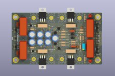
It is similar indeed, except for using the OPA instead of quad transistors , although it seems smaller, it does not automatic adjusting of positive and negative voltages. Each rail has its own regulator. Also it does not have the electronic capacitor filter (Q1, Q2 on our design), but it should work pretty much the same. I'll reduce in the future the 0,47 Ohm series resistor to 0,1 or even less ... which are these wich create a small voltage dropout .
0R1 wouldn't be bad already. I have plenty in stock too. 😉
660-BPR58CR10J
Or remove them in v2 as we discussed.
660-BPR58CR10J
Or remove them in v2 as we discussed.
I don't have any in stock, so I need to buy from the store. But yes, 0,1 Ohm was my very first thought.
I put these values on the Q17-Turbo.
I still believe that for better performance, the MOSFET should be paired. Which I don't like.
I still believe that for better performance, the MOSFET should be paired. Which I don't like.
Last edited:
Hmm, shows you don't really fully understand what a power supply is... it's in series with the signal... so, absolute audio frequency "modulation"...Oh no problem ! Don't worry, we can prolongue the terminals ... since there is no audio frequencies, it does not influence at all.
... and also contradicts your previous statement: "I could only listen music to a lower level then desired, or to listen music which does not have unexpected peaks on low bass or extreme high frequencies."
//
I can't be an expert in everything ... but it is more important the length of Q17 mosfet terminals then of the Sigma 22. And they are longer almost to entire lenght of those transistors because I can't have access to the screws.
I'm a little confused with the max deliverable current. In the 1st post it says 3A. In a later post it says limited by MOSFET Rds(on).
Is that the short-circuit current?
How much current can it deliver to a load before running out of regulation? There must be a thermal limit somewhere?
Do you have any measurements on this supply, words are easy but where's the performance?
The numbers given in post #2 show a rather high drop above a few amps, so is this a 3A regulator?
Jan
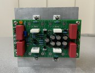
I tested as in the 3D drawing. With 10mm PCB spacers, the transistor protrudes a maximum of 16mm. By pushing it inwards, you can go down to 6mm. Just enough to screw it. It is also possible to put them vertically with an external heatsink on each side of the board.
Moor, you can output your photos and video. 😉
Moor, you can output your photos and video. 😉
Last edited:
- Home
- Amplifiers
- Power Supplies
- Q17 Sigma22 Regulated Ultrastable Ultralow Noise Linear Power Supply +-50/60Vcc