If you do this, than please use latest 2.9 ver fm github.
Hi Tibi,
The file his not online. This was the old version with the wrong result I built last year. I've to find time to update it. May be someone will try it. 😉
Stef.
Considering that the coil must cover 20Hz-20KHz, a flat coil will perform considerably better than a 1mm wirewounded coil. Due skin effect, geometry and area are most important. The shape of flat coil will have larger surface area and proper geometry for high frequency operation.
If you want to calculate precisely, there are various tools on the net for such.
Hope this answer your question.
Question in the round, who has made the direct comparison between printed coil and wound wire coil on the Q17?
I have made this comparison and can see that with the wire coil the amp gains in foundation and control and a bit of sparkle.
From the idea, it is true that a thinner conductor performs better on the skin effect, only that is only part of the job the coil has to do. If we connect the speakers to the amplifier with bell wire, the bell wire is better shielded and has more suitable behavior at the skin effect, but it still doesn't sound.
So if I want to optimize the coil of the Q17 there is silver plated enameled copper wire, this has a lower resistance only due to the skin effect or there is the slightly larger twisted wire bundle of black enamel wire (thermally bonded enameled copper wire), which was developed under the name Tritec, and not to forget, today's solution for electric motors, which are rectangular wire bundles of twisted black enamel wire. Compared to the old Tritec, these have the advantage that they can be wound tighter and thus the coils work more ideally.
Of all the variants, the printed coil is the least favorable. A major point of the printed coil is the large stray field (this is used for induction hotplates, because here the large magnetic field is important to heat the pot), which is large compared to a cylindrical coil. With this I get additional disadvantages, because this coil can be contaminated with disturbances much easier than the cylindrical wire coil. Also, there is a function between an aluminum body that is orthogonal to the axis of the coil. This is the case with the printed coil. Therefore, depending on the distance between the coil and the heat sink, current is induced into the aluminum heat sink in the Q17, which is simply converted into heat due to the property of aluminum. Practically, it is the same effect as the magnetic brakes of trains or for induction hotplates. For the Q17 this means that it finds even more resistance than the measured DC resistance of the coil.
Regards Tim

Tibi,
in the BOM on the mouser you indicate BP 100uF, so I want to ask:

Which option would you recommend as better:
in the BOM on the mouser you indicate BP 100uF, so I want to ask:
Which option would you recommend as better:
- C2+C22 (220uF BP)
- C2 (jumper) + C22 (100uF BP)
Hi Folk,
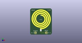
You will find on this link, the file to make a independent PCB of the 1.2uH flat coil for the Q17. It is experimental as I have not printed or tested it. This coil fit on Q17-MIni and Q17-Turbo PCBs.
https://github.com/stefaweb/Q17-a-QUAD405-audiophile-approach/tree/main/Q17-PCB-Coil
Stef.
You will find on this link, the file to make a independent PCB of the 1.2uH flat coil for the Q17. It is experimental as I have not printed or tested it. This coil fit on Q17-MIni and Q17-Turbo PCBs.
https://github.com/stefaweb/Q17-a-QUAD405-audiophile-approach/tree/main/Q17-PCB-Coil
Stef.
Attachments
Tibi,
in the BOM on the mouser you indicate BP 100uF, so I want to ask:
View attachment 1171184
Which option would you recommend as better:
Thank You!
- C2+C22 (220uF BP)
- C2 (jumper) + C22 (100uF BP)
Hi!
I did some tests on scope in the past with BPs and polarized capacitors. Best is a single 100uF 16v BP (we see especially a big difference on the low frequencies).
Stef.
Stef, Tibi, I like the idea of the external flat coil a lot as it seems to save precious pcb space. Like this it must be considerably easier to squeeze either of your 2-pair boards into my 80mm chassis. What would then be coil pcb's optimal orientation and minimum distance from whichever sensitive parts? Thanks, MiklosHi Folk,
You will find on this link, the file to make a independent PCB of the 1.2uH flat coil for the Q17. It is experimental as I have not printed or tested it. This coil fit on Q17-MIni and Q17-Turbo PCBs.
https://github.com/stefaweb/Q17-a-QUAD405-audiophile-approach/tree/main/Q17-PCB-Coil
Stef.
Dear Stef,
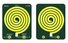
are you completely sure that the pcb coil in the jpg image in #1727 is an equivalent replacement of the original? I just noticed that it looks considerably different from the one integrated in Tibi's design (number of windings and probably overall size, too).
Thanks, Miklos
are you completely sure that the pcb coil in the jpg image in #1727 is an equivalent replacement of the original? I just noticed that it looks considerably different from the one integrated in Tibi's design (number of windings and probably overall size, too).
Thanks, Miklos
I seem to remember that there was also the two board model as a package, so a four layer coil, could it be that the layout for that is in #1727?
Hi,Hello,
I got IXTH48P20P and made measurements, also FQA36P15 and FQA46N15 for comparison
Regards Tim
I installed the IXTH48P20P and have been listening to it for a few days. The two amplifiers are essentially the same, but the large electrolytic capacitors are from different brands, which also has an influence. Therefore, my conclusion is that I can say that the IXTH48P20P are not very different from the FQA36P15. I only have a pair of power mosfet each. When building with the IXTH48P20P I paired the FQA46N15 related to Vgs(on). For me, the IXTH48P20P are an equivalent replacement, but I can't hear any "advantage" for me, both MosFETs seem to be too similar.
Regards Tim
Dear Stef,
are you completely sure that the pcb coil in the jpg image in #1727 is an equivalent replacement of the original? I just noticed that it looks considerably different from the one integrated in Tibi's design (number of windings and probably overall size, too).
Thanks, Miklos
Hi Miklos,
There seems to be a problem. I took the file here to make the PCB 1.0:
https://github.com/tiberiuvicol/Q17-audiophile-amplifier/blob/main/KiCad source/Q17.kicad_pcb
But I just saw that there is a second different one here (called 2.8):
https://github.com/tiberiuvicol/Q17-audiophile-amplifier/blob/main/Q17_2final/Q17_2final.kicad_pcb
So I don't know which one is the right one!!
I'm removing the files from my Github for now.
Tibi, HELP !!!
Stef.
Attachments

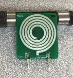
Hi Stef, I spotted the difference in the pcb photo recently provided in #1525 by HRDSTL. The latter seems to be more similar to the right hand side coil version in your attached image (sc.png) above. Let's see what Tibi will say.
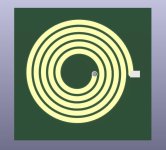
I exported the footprint of the coil with tinned surface
I checked, this coil is old!
I checked, this coil is old!
Attachments
Last edited:

Hello!
Here is the correct version with the last Tibi coil footprint.
https://github.com/stefaweb/Q17-a-QUAD405-audiophile-approach/tree/main/Q17-PCB-Coil 1.1
Have fun!
Stef.
Here is the correct version with the last Tibi coil footprint.
https://github.com/stefaweb/Q17-a-QUAD405-audiophile-approach/tree/main/Q17-PCB-Coil 1.1
Have fun!
Stef.
Attachments
- Home
- Amplifiers
- Solid State
- Q17 - an audiophile approach to perfect sound