I think you have an working amplifier, but you are too afraid to power up. 🙂One quick update, removed the 10k resistors and replaced with 100R on R29/30. Now with the bulb tester across the 0.1R in series with the positive rail I get only 0.1mV but the bulb is still glowing. Offset is around 0.1mV and the FQA36P15 power mosfet is getting warm but the opp mosfet is not getting warm during this test after 10-15mins. Voltages across the 47/1w resistor is around 2.32v. Rechecked all the transistors and they all seem to be fine and no shorting anywhere. Any other pointers in terms of why the bulb tester is not switching off or should ideally glow less brighter with now less than 0.1mV flowing right now.
Thanks
What is the resistance of the bulb and resistance of the trafo primary ?
Regards,
Tibi
A quick look at your schematic and I measured the Mirror CCS current across R3/150R which is 1.9mV and class A bias stage across R13/10R which is 469mV. These values with the bulb tester being used.Look at this uptodate diagram.
It must match your PCB (except Q12/R42/R43) with the same numbering but with references of available component.
https://github.com/stefaweb/Q17-a-QUAD405-audiophile-approach/blob/main/Q17-Mini-schematic.pdf
Regards,
Stef.
Thanks
I know Tibi I am mostly always been a Class A guy and always see the bulb being completely off or very low brightness because of the low bias trimmer set for initial power up and testing 🙂I think you have an working amplifier, but you are too afraid to power up. 🙂
What is the resistance of the bulb and resistance of the trafo primary ?
Regards,
Tibi
Over R3 you need to have ~600mV. Same over R13.A quick look at your schematic and I measured the Mirror CCS current across R3/150R which is 1.9mV and class A bias stage across R13/10R which is 469mV. These values with the bulb tester being used.
Thanks
Q17 is a completely different amplifier that can be tested only as whole. You can not disconnect a section and have the amplifier working.
Putting light bulbs here and there is a nonsense.
This is how I'll do:
Make sure that I have mounted all the parts correctly, short input in order to avoid any peak noise, mount fuses on positive and negative rails and power up the module.
Regards,
Tibi
Very fast the smoke. 😉
I should have taken pictures the last time I got this. The two resistors R13 and R32 have been cut in half by their rapid combustion.
Use 1A fuse on neg and positive rail for testing and nothing will burn except the fuses.
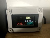
For my tests, I have this wattmeter in front of the power supply on the main.
It's very practical. When you switch on the amp, you see the consumption in real time.
For the Q17, it starts with a few Watts, then jumps sharply to around 25/50W, then back down to 14-16W. If after one and a half seconds, there is more Watts (like 50W, 100W, 300W), you must cut off immediately if the fuses have not blown.
Stef.
I should have taken pictures the last time I got this. The two resistors R13 and R32 have been cut in half by their rapid combustion.
Use 1A fuse on neg and positive rail for testing and nothing will burn except the fuses.
For my tests, I have this wattmeter in front of the power supply on the main.
It's very practical. When you switch on the amp, you see the consumption in real time.
For the Q17, it starts with a few Watts, then jumps sharply to around 25/50W, then back down to 14-16W. If after one and a half seconds, there is more Watts (like 50W, 100W, 300W), you must cut off immediately if the fuses have not blown.
Stef.
Attachments
Last edited:
He has a lamp instead of fuses. And it shows that there is a problem with the amplifier. It's not working.ничего не сгорит, кроме предохранителей.

Can I use a IRFP9610 in place of FQP3N30 and 610 in place of FQP3P20? As one of the other members pointed out I used these and me too now suspecting them. I am sure that I have genuine 610/9610 mosfets.
thanks
thanks
IRF9610 is P channel MOSFET and may replace FQP3P20
IRF610 is N channel and may replace FQP3N30
Take care on parts, otherwise there will be indeed smoke. ;-)
Regards,
Tibi
IRF610 is N channel and may replace FQP3N30
Take care on parts, otherwise there will be indeed smoke. ;-)
Regards,
Tibi
Yes I will replace FQP3N30 between the pairs of IRF9610 with the IRF610 and the same with the other side replace FQP3P20 with the IRF9610 between the pairs of IRF610 mosfets right?

I guess you blew up few boards so you should be knowing by now where the issue is right?I don't think replacing it will help.
As you suggested in one of your posts except the FQP3N30/FQP3P20 are the only mosfets which are from very old stash the rest of the parts and transistors are from genuine sources. I feel my stock of FQP devices may not be able to run more current than like 100-200mA which I used them in Salas BiB psu boards. So I thought of replacing them with 610/9610 where I have genuine ones.
I never found out. Replacing it with an IRF didn't help me. Moreover, the mini version ran fine, but the meander was crooked and the sound was not good. And then the output transistors just burned out, for no reason. I decided that the problem was with the boards. Here at the beginning of the thread a lot of people made their boards, but we did not see any results.
As I understand it, none of these boards have been run. Or maybe people just didn't share the results.


Hello SMK,I never found out. Replacing it with an IRF didn't help me. Moreover, the mini version ran fine, but the meander was crooked and the sound was not good. And then the output transistors just burned out, for no reason. I decided that the problem was with the boards. Here at the beginning of the thread a lot of people made their boards, but we did not see any results.
The circuit has a very high oscillation potential and I have also burnt out my output mosfet exclusively through high-frequency oscillation. I have simulated the circuit very extensively and tried many options, so I have now also found a fairly stable variant. With Tibi's design, I assume that he is only realising the amplifier because of the quality of his components, especially the capacitors. If the capacitors have a high resistance in the MHz range, then the oscillations are damped and it sounds great - this is also how a lot of crossovers are constructed, in that capacitors of inferior quality compensate for the distortions of drivers and in the end the result sounds good.
The amp has a lot of acoustic potential but it's not at all trivial to uncover it, so I've already built 10 of them, only 4 of them play, the rest was gaining learning experience.
Regards Tim

I tested the amp by removing the bulb tester but putting a 1A fuse in each of DC rails. The fuses blew up and I see that the leds on the board lit up fine during this period. But looks like the amp board has some issues 🙁
Bad news.
It seems to be more complicated to make a PCB that works with MOSFETs than bipolars. The Q17 is full of MOSFETs. My Q17-Mini runs smoothly and is reliable over time. My first version of the Q17-P2 does not work. It swings in all directions. I made a second version with a very optimized PCB. It may work but for the moment I don't have the budget to make one and I prefer to spend my money improving the Q17-Mini which is good enough for most people.
Regards,
Stef..
- Home
- Amplifiers
- Solid State
- Q17 - an audiophile approach to perfect sound