The 3P20 is dead. The 3N30 is ok.
I don't think I reversed the transistors. I have others I will change it.
Stef.
I don't think I reversed the transistors. I have others I will change it.
Stef.
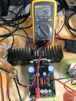
With the new Q5/Q6, no more R8 smoke. 10W on the main wattmeter.
R7/R8 at 20°C.
-40V at speaker output.
May I try to solder back Q15/Q16 now?
Stef.
R7/R8 at 20°C.
-40V at speaker output.
May I try to solder back Q15/Q16 now?
Stef.
I measured R13 at 0.617v. Afterwards, I did not have time to take the other measurements because R10 has smoke. I cut.
I will look at that later. Thank you.
Stef.
I will look at that later. Thank you.
Stef.
Even without power transistors, having -40V at output indicate that Q6 is saturated.
This may be related to a problem in mirror Q9&Q11 or cascode Q8&Q7. Check these transistors and make sure are correctly mounted.
Maybe is worthing to check BS250 pinout.
Regards,
Tibi
This may be related to a problem in mirror Q9&Q11 or cascode Q8&Q7. Check these transistors and make sure are correctly mounted.
Maybe is worthing to check BS250 pinout.
Regards,
Tibi
Hello Jan and folks!
The BD139 is a plastic package and is not connected to heatsink.
I did not have time to resume my tests last night. I just checked Q9 / Q11, Q7 / Q8. They are ok and pinout seems ok. I changed R11, R12, R10 and R13 who smoked. They were only half their face value.
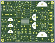
When I check the PCB against the schematic in KICAD, I have no errors. I have worked everything and checked the KICAD files so much that I don't even have any CRC errors in KICAD PCB anymore.
The files are available on Github. The online version 1.0.9 is almost the same as the 1.0.8 which I used to make the proto PCBs. The difference is new footprints for Q8, Q9 and Q11, thicker tracks and comestic details on the silkscreen.
I may be able to make a power supply around 20V with what I have in stock at home. I'm a little fed up with changing burnt components all the time and I'm short on some.
I'll keep you informed.
Stef.
The BD139 is a plastic package and is not connected to heatsink.
I did not have time to resume my tests last night. I just checked Q9 / Q11, Q7 / Q8. They are ok and pinout seems ok. I changed R11, R12, R10 and R13 who smoked. They were only half their face value.
When I check the PCB against the schematic in KICAD, I have no errors. I have worked everything and checked the KICAD files so much that I don't even have any CRC errors in KICAD PCB anymore.
The files are available on Github. The online version 1.0.9 is almost the same as the 1.0.8 which I used to make the proto PCBs. The difference is new footprints for Q8, Q9 and Q11, thicker tracks and comestic details on the silkscreen.
I may be able to make a power supply around 20V with what I have in stock at home. I'm a little fed up with changing burnt components all the time and I'm short on some.
I'll keep you informed.
Stef.
Hello!
Very nice the new forum interface.
This is just to tell you that I found the problem on the prototype board. Q12 (BD139) was mounted upside down.
So I had two concerns. The 3P20 in Q5 was defective on arrival and Q12 was mounted upside down.
The board is working. Offset at output is 0.040v. Curves on scope are ok.
I fixed the PCB silkscreen for Q12. The production PCB version 1.1.1 is now available on my Github repository for those who want it.
Cheers,
Stef.
Attachments
Last edited:
Stef, Great news !!Hello!
Very nice the new forum interface.
This is just to tell you that I found the problem on the prototype board. Q12 (BD139) was mounted upside down.
So I had two concerns. The 3P20 in Q5 was defective on arrival and Q12 was mounted upside down.
The board is working. Offset at output is 0.040v. Curves on scope are ok.
I fixed the PCB silkscreen for Q12. The production PCB version 1.1.1 is now available on my Github repository for those who want it.
Cheers,
Stef.
Hi!
I am not very happy. I had ordered 6 FQP3P20 from Mouser and out of the 6, 3 are DOA.
I had a question. In Q9 / Q11 we can put BS250P or ZVP2106A. Which one is the best? Or will it be the same result?
Stef.
I am not very happy. I had ordered 6 FQP3P20 from Mouser and out of the 6, 3 are DOA.
I had a question. In Q9 / Q11 we can put BS250P or ZVP2106A. Which one is the best? Or will it be the same result?
Stef.
Congratulations Stef !...
This is just to tell you that I found the problem on the prototype board. Q12 (BD139) was mounted upside down.
So I had two concerns. The 3P20 in Q5 was defective on arrival and Q12 was mounted upside down.
The board is working. Offset at output is 0.040v. Curves on scope are ok.
...
If Q12 was mounted upside down, Q6 got saturated. These are low Rdson transistors and trough Q5 you got almost 1A. Continuous power dissipated by Q5 reached over 50W and power dissipated by R10 reached 10W.
If you use OPA1641, offset voltage should be ~1mV. Quality of C2 and C7 matter as well.
Q13 and Q14 will dissipate around 400mW. I do not think there is need for heatsinks.
Regards,
Tibi
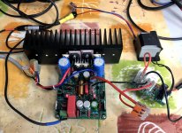
The heatsink in the photo for Q13 / Q14 was for fun. In the end, there doesn't seem to be a need for it and in addition it prevents the components around to breathe.
In the last version of the PCB I added holes for C7. You can put lots of different capacitors
Stef.
In the last version of the PCB I added holes for C7. You can put lots of different capacitors
Stef.
Attachments
Last edited:
Not yet. I am waiting for the final PCB versions to build two boards.
The sound seems very good at first glance. The board does not heat up and the power transistors are at 34°C with the small black heatsink that I put.
There is just something weird. When I turn on the board, the two LEDs light up then D1 flashes once a second later.
Stef.
The sound seems very good at first glance. The board does not heat up and the power transistors are at 34°C with the small black heatsink that I put.
There is just something weird. When I turn on the board, the two LEDs light up then D1 flashes once a second later.
Stef.
Hello Tibi,Congratulations Stef !
If Q12 was mounted upside down, Q6 got saturated. These are low Rdson transistors and trough Q5 you got almost 1A. Continuous power dissipated by Q5 reached over 50W and power dissipated by R10 reached 10W.
If you use OPA1641, offset voltage should be ~1mV. Quality of C2 and C7 matter as well.
Q13 and Q14 will dissipate around 400mW. I do not think there is need for heatsinks.
Regards,
Tibi
I always have 40 mV DC offset, this has always been the same for all my setups.
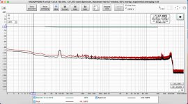
IMD may make sense.Would be nice to see some THD/IMD measurements !
Do you associate good sound with THD ?
I personally associate good sound with proper harmonic distortion distribution, so a FFT is much appropriate.
Regards,
Tibi
Last edited by a moderator:
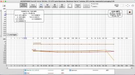
I have done these measurements yesterday but am not very good at using REW.
40mV for me too.
Stef.
40mV for me too.
Stef.
Attachments
Last edited:
ZVP2106A is a better device....
I had a question. In Q9 / Q11 we can put BS250P or ZVP2106A. Which one is the best? Or will it be the same result?
...
My choice for 2N7000 and BS250P was availability and cost. These are old parts available from multiple manufacturers.
Because these are used in upper cascode and current mirror, their impact on the final sound is minimal.
Regards,
Tibi
- Home
- Amplifiers
- Solid State
- Q17 - an audiophile approach to perfect sound