Hi Tim!
Is it correct or not in the PCB? 😕
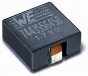
I saw that in a PCB you made, you use an SMT inductor. Does it work well? Do we need to sort them out to have the value closest to 1.2uH?
744313120 Wurth Elektronik | Mouser France
I am still looking for a trade inductor to put on my card. I was also thinking of using an SMT inductor but I don't know which model to choose from Mouser. There are still 129 1.2uH power inductor models available on Mouser !
I have about 30mm of length available on the PCB. I was thinking of taking one of these inductors and soldering it on two 1m2 wires and after that soldering it on the PCB
Stef.
Is it correct or not in the PCB? 😕
I saw that in a PCB you made, you use an SMT inductor. Does it work well? Do we need to sort them out to have the value closest to 1.2uH?
744313120 Wurth Elektronik | Mouser France
I am still looking for a trade inductor to put on my card. I was also thinking of using an SMT inductor but I don't know which model to choose from Mouser. There are still 129 1.2uH power inductor models available on Mouser !
I have about 30mm of length available on the PCB. I was thinking of taking one of these inductors and soldering it on two 1m2 wires and after that soldering it on the PCB
Stef.
Attachments
Last edited:
Hello Stef,
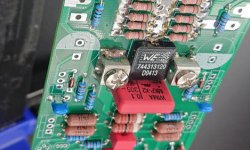
I didn't get a good quality BS250 at Reichelt.de - where I buy almost all components - so I use the alternative types of MosFET from Diodes in my setups from No. 2 onwards. You can see this well on my P2 board.
Q17 - a QUAD405 audiophile approach to perfect sound
The alignment on your layout are the BS250s that Tibi named as "sold out".
I have the advantage of having large quantities of coils, so I use self-wound air core coils for my Q17. These are made of 1mm enamelled wire which I wind 13 times around a 12mm tube. So a Edding would fit in terms of diameter. 1.5 m of wire should be enough for two coils.
I only find core coils on Mouser and these reduce the sound quality. What is very expensive, but basically has potential, as it is based on iron - so could have a rather pleasant distortion spectrum - is the IHDM1008BCEV1R2M30. However, it is the case that with very few windings, the clanking spectrum of the core material can be heard very clearly. Therefore, this coil is also not suitable for "high end". Enamelled copper wire is also not expensive at Reichelt.de.
Security Check
The hardest part is not the winding, but the scraping off of the enamel so that the solder holds.
Regards Tim
Thanks Tibi
Hi Tim!
Thanks for the informations. For me, the hardest part is going to be finding a 12mm tube. 😉
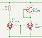
For the BS250P, juste to be sure. The new schematic with the DIODES INC version is like this?
Stef.
Hello Stef,
Basically I haven't changed the circuit, only added very little. The small-signal MosFETs are original from Tibi.

Regards Tim
Thanks you Tibi.
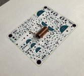
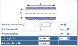
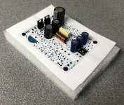
About the coil. I finally built a 22 turns coil with a diameter of 8mm and a length of 22mm. I used the online calculator. It fits right on the board.
Cheers,
Stef.
Attachments
Last edited:
Stef ,
If you make the coil diameter 12mm then it will fit even better, just use a 12mm drill bit wind it.
If you make the coil diameter 12mm then it will fit even better, just use a 12mm drill bit wind it.
Hello Jan!
I don't have enough room for a 13mm coil (D: 12 + 1mm of wire). I've a space of 9x25mm on the PCB
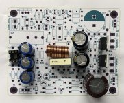
I buil a test coil of D: 9mm x 18 turns of 1mm2 wire. I could not measure it because I no longer have an insultaded 1mm2 cable. I used a regular wire.
If you want to look at my PCB, it is available on my Github account:
GitHub - stefaweb/Q17-a-QUAD405-audiophile-approach: Q17 is an error correction amplifier based on the QUAD405 current dumping principle
I still have some work to verify that the components are not too stuck to each other.
Stef.
I don't have enough room for a 13mm coil (D: 12 + 1mm of wire). I've a space of 9x25mm on the PCB
I buil a test coil of D: 9mm x 18 turns of 1mm2 wire. I could not measure it because I no longer have an insultaded 1mm2 cable. I used a regular wire.
If you want to look at my PCB, it is available on my Github account:
GitHub - stefaweb/Q17-a-QUAD405-audiophile-approach: Q17 is an error correction amplifier based on the QUAD405 current dumping principle
I still have some work to verify that the components are not too stuck to each other.
Stef.
Attachments
Hello!
Several of the components of Q17 appear to be unavailable with an unknown delivery date.
BS250P (Diodes Inc or Vishay)
OPA1641AIDR
KSC1845FTA
2N7000TA
I searched Digikey, Mouser, Farnell and RadioSpare. Yesterday there were BS250P and OPA1641AIDR in stock at Mouser and someone bought it all. 😡
Stef.
Hello Stef,
You can get a lot of it at Reichelt.de.
IRF 610 VIS
SA 992 (KSA992)
SC 1845 (KSC1845)
IRF 9610
ZVN 4206A (2N 7000 FAI)
ZVP 2106A (BS 250)
From RS-online I get the:
FQP3N30
And from Mouser the OPA1611
You can get a lot of it at Reichelt.de.
IRF 610 VIS
SA 992 (KSA992)
SC 1845 (KSC1845)
IRF 9610
ZVN 4206A (2N 7000 FAI)
ZVP 2106A (BS 250)
From RS-online I get the:
FQP3N30
And from Mouser the OPA1611
Last edited:
Thanks Tim.
I should get by with one order from RS and another from Mouser.
I have a quick question regarding KiCAD. What should be used in the software to make small ventilation holes below the components that heat up?
Stef.
I should get by with one order from RS and another from Mouser.
I have a quick question regarding KiCAD. What should be used in the software to make small ventilation holes below the components that heat up?
Stef.
Hello Stef,
As an engineer for building physics, I can tell you that you cannot use "ventilation holes" to effect cooling in your layout.
What is possible is what Sorinsistem implements in his PCB (Q17 - a QUAD405 audiophile approach to perfect sound + Q17 - a QUAD405 audiophile approach to perfect sound) by dissipating the heat from the directly connected SMD components to the other side of the PCB via the vias and thus increasing the heat-radiating surface.
In my design for your small PCB task, I chose very compact coolers for the transistors that get warm, so that these transistors also do not get relevantly warm.
Last edited:
Hi!
Finally, it was a bad idea this story of holes under the components if you use "Through Hole" version. I was thinking of doing this for R11 and R12 but I don't have room on the PCB anyway.
I am going around the components.
Since there are quite a few supply issues and many of the components on the Tibi diagram are "obsolete", I made a list.
Is this list good and are there others equivalences (especially for low power transistors)?
U1 = OPA1641 or OPA1611
Q1, Q6, Q13 = IRF610 or FQP3N30
Q2, Q7, Q12 = 2SA970 or KSC1845
Q12 = 2SC2240 or AC181
Q4, Q5, Q14 = IRF9610 or FQP3P20
Q8 = 2N7000TA or ZVN4206AV
Q9, Q11 = BS250P or ZVP2106A
Q10 = KSA992
Q15 = FQA46N15
Q16 = FQA36P15
These ones are obsoletes.
2SA970
2SC2240
AC181
The KSC1845 seems to be only available in "Kinked Lead" (KSC1845FTA) which poses a problem with the PCB footprint.
I also found that Q12 is missing from the BOM given in the Q17.pdf file.
Stef.
Last edited:
Hello,
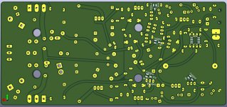
I have another idea for the problem that there is always some component that is not available. Therefore, I have added the SMD solder pads for the SMD version of the small transistors to the PCB. I assume that these are equivalent to the large ones. The power dissipation of the SMD transistors is given as 300mW, which is surely sufficient, isn't it Tibi?
Regards Tim
Attachments
Hello!
Found another error in the Q17.pdf doc.
We can read in the BOM list:
Q2,7,12 - KSC1845 + link to mousser.
But on the schematic, Q2 is a PNP (2SA970). Should be a KSA922 instead?
Stef.
ps: new version of files available on my Github fork.
Found another error in the Q17.pdf doc.
We can read in the BOM list:
Q2,7,12 - KSC1845 + link to mousser.
But on the schematic, Q2 is a PNP (2SA970). Should be a KSA922 instead?
Stef.
ps: new version of files available on my Github fork.
Last edited:
One more.
Still in the Q17.pdf doc.
We can read this but Q12 is a plastic TO-92!!
Stef.
Still in the Q17.pdf doc.
We can read this but Q12 is a plastic TO-92!!
Stef.
Code:
Q12 must be mounted on heatsink too, as it will be used to compensate final stage
thermal run away.- Home
- Amplifiers
- Solid State
- Q17 - an audiophile approach to perfect sound