Hello
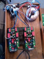
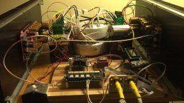
I have now assembled a pair of Q17 and played around with them a bit and tested out how I like them best. Now they play great and my old amps are really old now. I must admit that I have yet to be able to hear an amp that could do both the outstanding control of the drivers and in addition play highly accurate in all ranges, but never boringly nudging.
Regarding what I said about C2 and possible other parallel capacitors, my tests and queries with Tibi have taught me better. A parallel MKP does not sound, it leads to feedback of the mid-high. Also my output installation with 100uF Panasonic FR did not sound either. I do not have the 100uF Muse used by Tibi, so I could not test it out. A 100uF Audio Electrolyth capacitor for crossovers also sounded pretty much like feedback. The variant of two 220uF Panasonic FR connected in series with the polarities reversed sounds very good. I now have that as a flying setup on the board....
The setup is not yet well suited for the case. I still want to provide the MosFET Q13 and Q14 with a small heat sink, this is much easier in the assembly, than all MosFET screwed on only one heat sink and then soldered.
What I must add is that I have not yet heard the sound that the amplifier plays at +-50V. I have only +-35V so far and it is already great. But I also have R24+R25 together reduced to 8k ohms. So the Q5 and Q6 get warm, but not more. At normal volume the four output transistors stay cold, I find that very remarkable. I paired the output transistors related to Vgs to 2mV difference, more was not possible. Admittedly, the tolerance of my measuring device is also in this range and it is also clear that this value can be easily influenced by little temperature change. So I always have to avoid touching the transistors when pairing so they all stay the same temperature.
Here a picture of the test setup.
Regards Tim
Attachments
Thank you for your feedback and contribution, Tim.
As now you know the sound of the amplifier, I suggest you to try synchronous rectification. I have posted here source and gerbers for a THT version Ideal bridge rectifier GB
Regards,
Tibi
As now you know the sound of the amplifier, I suggest you to try synchronous rectification. I have posted here source and gerbers for a THT version Ideal bridge rectifier GB
Regards,
Tibi
I'm not sure, if this schematic, accept Laterals one, revised the layout including this option and others . 🙂
Regards,
Alex
Regards,
Alex
Attachments

Last edited:
Yes, will work with lateral mosfets in place of Q5 and Q6. No schematic changes are needed.
It will work with laterals in place of Q15 and Q16 too, in this case R11 and R12 need to be changed to 10ohm.
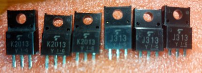
On other hand, I'm not sure that 2SJ313 and 2SK2013 are laterals. However, they are very linear and will sound just great.
Regards,
Tibi
It will work with laterals in place of Q15 and Q16 too, in this case R11 and R12 need to be changed to 10ohm.
On other hand, I'm not sure that 2SJ313 and 2SK2013 are laterals. However, they are very linear and will sound just great.
Regards,
Tibi
At normal volume the four output transistors stay cold, I find that very remarkable.
Have you measured the distortion at low power?
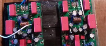
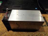
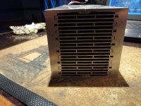
This beast is an implementation of Q17 with laterals, dual mono in class A/B.
Each trafo is 1200VA followed by synchronous rectifiers, 2 x Mundorf MLytic 47000uF/100V.
Boards are equipped with 4 pairs of duble die Exicon. Each mosfet is biased @ 300mA. Front opamp is Burson Vivid V6.
Lot of power and juice !
Regards,
Tibi
Each trafo is 1200VA followed by synchronous rectifiers, 2 x Mundorf MLytic 47000uF/100V.
Boards are equipped with 4 pairs of duble die Exicon. Each mosfet is biased @ 300mA. Front opamp is Burson Vivid V6.
Lot of power and juice !
Regards,
Tibi
Attachments
Have you measured the distortion at low power?
Who listen at low power ? 😀
Regards,
Tibi

Tibi,
You'll laugh, I listen at low power, I've already thought about how to get the amp 10dB quieter. My controls are just not ideal at -60dB.
Distortion I have not measured, I have not measured the amp at all, however I cannot find that it plays audible distortion. However, I am aware that it is not trivial to measure such a circuit without measuring only the characteristics of the source and receiver. After all, sound cards are also limited in quality, regardless of the fortune they cost in money.
Hello
I have now assembled a pair of Q17 and played around with them a bit and tested out how I like them best. Now they play great and my old amps are really old now. I must admit that I have yet to be able to hear an amp that could do both the outstanding control of the drivers and in addition play highly accurate in all ranges, but never boringly nudging.
Regarding what I said about C2 and possible other parallel capacitors, my tests and queries with Tibi have taught me better. A parallel MKP does not sound, it leads to feedback of the mid-high. Also my output installation with 100uF Panasonic FR did not sound either. I do not have the 100uF Muse used by Tibi, so I could not test it out. A 100uF Audio Electrolyth capacitor for crossovers also sounded pretty much like feedback. The variant of two 220uF Panasonic FR connected in series with the polarities reversed sounds very good. I now have that as a flying setup on the board....
The setup is not yet well suited for the case. I still want to provide the MosFET Q13 and Q14 with a small heat sink, this is much easier in the assembly, than all MosFET screwed on only one heat sink and then soldered.
What I must add is that I have not yet heard the sound that the amplifier plays at +-50V. I have only +-35V so far and it is already great. But I also have R24+R25 together reduced to 8k ohms. So the Q5 and Q6 get warm, but not more. At normal volume the four output transistors stay cold, I find that very remarkable. I paired the output transistors related to Vgs to 2mV difference, more was not possible. Admittedly, the tolerance of my measuring device is also in this range and it is also clear that this value can be easily influenced by little temperature change. So I always have to avoid touching the transistors when pairing so they all stay the same temperature.
Here a picture of the test setup.
Regards Tim
Hi Tim,
Thanks for sharing your work.
Do we need additional coil? I thought you already got them drawn on your pcb.
Cheers
Attachments
Hi,
I wanted to test where the limits are, so I cut off the printed coil and wound a coil from 1mm enamelled wire. Yesterday I ordered new PCBs with printed coil as I recently published. With this I should actually get a very good result. The subjunctive is the fact that I create by geometry eddy currents in the heat sink and thus the loss of the coil will be higher. Whether that is relevant or not is difficult to determine. The stray field of the flat coil is large, that is certain.
I wanted to test where the limits are, so I cut off the printed coil and wound a coil from 1mm enamelled wire. Yesterday I ordered new PCBs with printed coil as I recently published. With this I should actually get a very good result. The subjunctive is the fact that I create by geometry eddy currents in the heat sink and thus the loss of the coil will be higher. Whether that is relevant or not is difficult to determine. The stray field of the flat coil is large, that is certain.
Great to hear that you're experimenting with the coil! Pls do let us know how your subjective listening impression changes with the two different types of L1.
In reference to stray field generated by the flat coil, does it influence the output stage in any perceivable way?
In reference to stray field generated by the flat coil, does it influence the output stage in any perceivable way?
Hi Alex,
I did a little investigation. 2SJ313 and 2SK2013 are vertical mosfets, therefore they exhibit a 0.7 Siemens forward transconductance which is low compared with Fairchid's FQP3N30/FQP3P20. I must admit that Fairchid's offer exceptional audio performance.
If you want to go for laterals the pairs are 2SJ76, 2SJ77, 2SJ78, 2SJ79 / 2SK213, 2SK214, 2SK215, 2SK216. They have superb liniarity at the cost of very low forward transconductance 0,035 Siemens. :-|
Another indicator of vertical vs lateral is the notation of pins. For verticals is GDS, while for laterals is GSD.
Regards,
Tibi
Tibi,
You'll laugh, I listen at low power, I've already thought about how to get the amp 10dB quieter. My controls are just not ideal at -60dB.
...
I was joking ! 😀
I also listen at very low levels. Most of the time under 1W. I do not hear any audible distortion, but these days I'll fire my generator and scope to see the truth. Current dumping help a lot, but there could be some crossover artefacts left.
Regards,
Tibi
Hi,
I wanted to test where the limits are, so I cut off the printed coil and wound a coil from 1mm enamelled wire. Yesterday I ordered new PCBs with printed coil as I recently published. With this I should actually get a very good result. The subjunctive is the fact that I create by geometry eddy currents in the heat sink and thus the loss of the coil will be higher. Whether that is relevant or not is difficult to determine. The stray field of the flat coil is large, that is certain.
You may separate the inductor PCB and mount vertically. This will save some space as well.
Regards,
Tibi
Hi Tibi
Would be there a diference in sound quality between toroid PS as in Q17 and smps PS as in QUASAR.
My idea is to disable Q13,Q14 and insert discharge diodes and supplay frontend with+-45V regulated toroid PS and output transistors with +-36V smps PS.
I hawe god expirience with regulated PS in amps.
Regards Bozo
Alex, are you going to build the amp ? Plse let us know how it goes, I need a project for this summer !😀
Hi Alex,
I did a little investigation. 2SJ313 and 2SK2013 are vertical mosfets, therefore they exhibit a 0.7 Siemens forward transconductance which is low compared with Fairchid's FQP3N30/FQP3P20. I must admit that Fairchid's offer exceptional audio performance.
If you want to go for laterals the pairs are 2SJ76, 2SJ77, 2SJ78, 2SJ79 / 2SK213, 2SK214, 2SK215, 2SK216. They have superb liniarity at the cost of very low forward transconductance 0,035 Siemens. :-|
Another indicator of vertical vs lateral is the notation of pins. For verticals is GDS, while for laterals is GSD.
Regards,
Tibi
Hi Tibi,
Thanks for your comments, appreciate . I have only tree pairs of 2SJ313 and 2SK2013 and intend to buy also FQP3N30/FQP3P20 . PCB are on the way from JLPCB . 🙂
Vrystaat @
Yes I intend to build, and I'll post my results here .
Regards,
Alex
Last edited:
thanks Alex,
Much appreciated and looking forward to your observations, I have allway's wondered about the sound of the current dumping principle, almost tried one of Dr Bora's current dumping projects. I'll wait for this one !😉🙂
Much appreciated and looking forward to your observations, I have allway's wondered about the sound of the current dumping principle, almost tried one of Dr Bora's current dumping projects. I'll wait for this one !😉🙂
Hi Tibi
Would be there a diference in sound quality between toroid PS as in Q17 and smps PS as in QUASAR.
My idea is to disable Q13,Q14 and insert discharge diodes and supplay frontend with+-45V regulated toroid PS and output transistors with +-36V smps PS.
I hawe god expirience with regulated PS in amps.
Regards Bozo
Hi Bozo,
Yes, there is a sound quality difference between linear PS and SMPS. I'll not go into details. What I suggest you is to use SMPS in the front end and linear on output transistors, because front end have a constant current drain and SMPS will handle this easy, while output stage will have large current peak's.
Regards,
Tibi
- Home
- Amplifiers
- Solid State
- Q17 - an audiophile approach to perfect sound