I understand your choices. It is my experience to get as much as possible out of the way of the air mass moving in and out, that is why i reacted.
Ideally something like this:
But it has to be possible in the first place. And regarding stiffness and enough material for bolting to leave material at the places of the bolts.
Anyway i am following your thread with interest.(i am considering replacing the drivers in my wwmt with purifi woofers and midrange)
Attachments
@JanRSmit, Jim's box should be fine, in theory. Only way to know for sure if taking in-box measurements, and comparing though. Have you had challenges with drivers of this size in boxes without big chamfers?
Btw Jim, your cabinet reminds me of of John Bower's team over at B&W. Here he is, standing next to his baby.

Some closer design detailing:


Apparently using computer modelling instead of trial and error, and laser interferometry to assess drive unit cones.
The whole top head could be rotated on top of the separate 27cm woofer cabinet, and there were knobs to adjust the midrange and treble level to all equalization for ease of placement. Also built in overload protection, with a button to reset things and get it back to work.
It would be fantastic to see how this measures in the modern era, complete with with 360 degree polars.
All these baffle drivers are sure to radiate very widely, with is the opposite of the flat baffle or waveguide (continuation of concave cone).
And this was all developed in mid 1970s, and released in 1979! But I guess man did go to the moon in 1969. I didn't even have a scientific calculator then.
Anyway, looking forward your continued build progress. Have you settled on woofer(s) yet?
Btw Jim, your cabinet reminds me of of John Bower's team over at B&W. Here he is, standing next to his baby.
Some closer design detailing:
Apparently using computer modelling instead of trial and error, and laser interferometry to assess drive unit cones.
The whole top head could be rotated on top of the separate 27cm woofer cabinet, and there were knobs to adjust the midrange and treble level to all equalization for ease of placement. Also built in overload protection, with a button to reset things and get it back to work.
It would be fantastic to see how this measures in the modern era, complete with with 360 degree polars.
All these baffle drivers are sure to radiate very widely, with is the opposite of the flat baffle or waveguide (continuation of concave cone).
And this was all developed in mid 1970s, and released in 1979! But I guess man did go to the moon in 1969. I didn't even have a scientific calculator then.
Anyway, looking forward your continued build progress. Have you settled on woofer(s) yet?
Last edited:
To go to the moon i was told the calculations were done by 3 ladies.
And speaker design then was indeed mostly trial and error , so took an awful lot of time ;-)
Anyhow regarding your question @tktran303 about chamfering, yes we had issues then (many years ago). If memory serves me, a sort of diffraction effect, and in the bass range it could add some noise because of the air moving back and forth passing the 'ridge' of the opening . It was audible.
Very narrow enclosures also was causing some audible effects.
Addendum: the sound waves on the outside get impacted by the baffle, a ridge will cause some disturbance easily measurable and in most cases audible. So on the inside this is also true, yet the directly audible effect has to go through the cone and surround to get to the outside. But it still occurs.
Then we used MDF for the cabinet, when also routed for flush mounting a mechanically stiff mounting of the driver could become a challenge. The quality of the MDF and thickness was for sure important.
Then we used MDF for the cabinet, when also routed for flush mounting a mechanically stiff mounting of the driver could become a challenge. The quality of the MDF and thickness was for sure important.
@hifijim
I take it you’ve seen this before?
http://www.troelsgravesen.dk/chamfer.htm
I’ve not seen other small studies in chamfering.
But the open basket and magnet to basket diameter makes me think you’ll be ok. (102mm/176mm)
On the other hand I would be more careful of the PTT5.25X, and as it’s frame is 1” smaller, yet it has the same magnet as the PTT6.5…
Last edited:

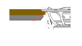
I did not see this before, thanks for sharing @tktran303 , but Troel's observations reminds me of a rule of thumb then that was the distance from chamfer to rim of chassis or magnet should be not less than the distance to the mounting flange or rim of basket. At that time we also had steel baskets and those were not very well (euphemistically stated ) in this aspect.
Thanks for pointing out the Troels link, yes I am familiar with that link.I take it you’ve seen this before?
http://www.troelsgravesen.dk/chamfer.htm
I’ve not seen other small studies in chamfering.
Regarding the chamfering on the inside of the mid driver hole: Sometime soon I will mount the driver and make near field measurements of the driver and of the box. I will make horizontal polar measurements, burst decay / CSD, and I will do an impedance sweep. The purpose of this is to look for structural and acoustic resonances, including any issues with the driver recess. If there is any measurable issue with the chamfer, it can be corrected rather easily with a Dremel tool.
I have always admired the B&W 801 speaker, from the original through the 801 Matrix-2 through the 801 Nautilus. I was not intending to copy the look, but when deep chamfering is applied to all six sides of a box, you get what you get.Btw Jim, your cabinet reminds me of of John Bower's team over at B&W. Here he is, standing next to his baby.
I am using my existing woofer cabinets. SB34NRX75-6 12” drivers in a sealed box, with LT eq. I am -3 dB at 27 Hz and -6 dB at 21 Hz.Anyway, looking forward your continued build progress. Have you settled on woofer(s) yet?
j.
More construction photos... I am working on the tweeter housing. I used my band saw to cut the circles rather than a router. Of course, cutting the driver recesses is a router job, so I waited for a sunny day and went outdoors for that.
Next step is glue up the 3 layers of wood circles, and profile the outer edge. I will be using a 1.5" radius router bit (37 mm) on the router table, with a specialized jig I made for positioning a circular work piece.


j.
Next step is glue up the 3 layers of wood circles, and profile the outer edge. I will be using a 1.5" radius router bit (37 mm) on the router table, with a specialized jig I made for positioning a circular work piece.
j.
I got to see the mockup foam baffle in person and the drivers. They are all smaller than I expected. I think this will look super neat when done (like all of your work).
@hifijim I hope you try an XO and spacing where the drivers do not need to be inverted and compare that to the 1.2X spacing and inverted. Or is the die cast?
@hifijim I hope you try an XO and spacing where the drivers do not need to be inverted and compare that to the 1.2X spacing and inverted. Or is the die cast?
I am not quite as experimental as you 🙂. Once I made measurements of the foam-board prototypes, I used simulation to layout the spacing and nominal crossover filters. Now I am building the finished cabinets, andthere will be no opportunity to adjust spacing or other geometries. The DSP filtering will be the only adjustable attribute. So yes, the die is cast.I hope you try an XO and spacing where the drivers do not need to be inverted and compare that to the 1.2X spacing and inverted. Or is the die cast?
Given the size of the Purifi PTT6.5M (177 mm) and the waveguide tweeter (170 mm), the closest CTC distance I could achieve in practice is about 175 mm with the drivers touching. At the expected crossover frequency of 1600 Hz, this is about 0.8 WL. If I include the size of the tweeter housing and the external dimensions of the midrange cabinet, it pretty much pushes the CTC up to 275 mm+, which is very close to 1.2xWL at 1600 Hz.
My current “best guess” simulations use measured polar data from the TW29BNWG waveguide tweeter in the sharp-edge foam donut, along with measured polar data of another 6.5” driver in a similar siz/shape box. These sims show the best response with a 1600 Hz 4th order filter, both drivers with the same polarity, and CTC spacing of 280 mm.
No, I had not seen that new video... thanks !
I glued up the 3 layers of cherry for the tweeter housings yesterday, and today I profiled the outer edge.... trial fit the tweeter.


I am still finalizing the design of the bracket/strut which will position the tweeter housing above and slightly in front of the midrange cabinet. If I was unconcerned with aesthetics, I could whip something up quick, but I want it to look good, so I am working through some sketches...
j.
I glued up the 3 layers of cherry for the tweeter housings yesterday, and today I profiled the outer edge.... trial fit the tweeter.
I am still finalizing the design of the bracket/strut which will position the tweeter housing above and slightly in front of the midrange cabinet. If I was unconcerned with aesthetics, I could whip something up quick, but I want it to look good, so I am working through some sketches...
j.
With the midrange box complete, I was finally able to make measurements of the Purifi driver (PTT6.5M04-NFA-01). The near field and time-gated polar responses are what I expected, with no surprises. There is none of the odd jumps in directivity as seen with the Satori MW16TX driver as we discussed in post #112 https://www.diyaudio.com/community/threads/purifi-waveguide-project.394174/post-7295782


--- --

This stage of measurement is important. This is the last opportunity to change the vertical spacing of the drivers, based on VituixCad simulation using the actual driver responses in the actual cabinets.
I investigated the cabinet structural performance with several tools. I was looking for any structural or acoustic (i.e. standing wave) resonances. First a mechanics stethoscope was used to probe the exterior surface of the cabinet while playing pink noise. This is an excellent tool to quickly give a qualitative assessment of any problems. If the sound through the stethoscope sounds very similar to the driver when playing pink noise, over the surface of the panel, then there are no significant issues with that panel.
If the stethoscope pink noise sound has a change in character compared to the driver’s pink noise, this reveals an issue to be further investigated. A poorly damped acoustical resonance will be present over much of the cabinet surface. A structural resonance, on the other hand, will be very location dependent.
I found one spot on the rear of the cabinet where the pink noise through the stethoscope had a slight emphasis in what I guessed was 500 – 700 Hz region. An impedance sweep revealed a small wrinkle at 640 Hz of about 0.08 Ohm, and a smaller wiggle at 520 Hz.

Based on these results, I used a nearfield microphone at the center of each panel. When looking at non-gated nearfield cabinet responses, it is helpful to try different levels of smoothing to see what is revealed. I found 1/6 octave smoothing to be most helpful in this case. The top, sides, and bottom had no pronounced peaks in output in the 500 – 700 Hz region. The rear panel had a + 6 dB peak at 620 – 650 Hz. Through the stethoscope, it did not sound like + 6 dB. But the question is this: Do I have a problem which I need to address?

When I compare the NF driver output to the NF cabinet output, the cabinet levels are about -24 dB below the driver. The rear cabinet wall radiation is generally lower than the side walls, and the 640 Hz peak that got my attention is only just equal to the side wall radiation at that frequency. The NF cabinet responses are so low that I am sure that much of what I measured is spillover from the driver, and also room modes. I am not adjusting the NF measurements to account for the size of the radiating surface. The rear wall is larger than the side walls, and the side walls are much larger than the driver. If I did attempt to account for the size of the radiating surface, the output of the side walls would be lower, and the rear wall output would be even lower. But the point of this is not to make an accurate measure of cabinet wall response (which would be very difficult), but to assess if I have a problem that needs to be addressed. A “Go-NoGo” indicator is very different than a calibrated measurement. Based on the preponderance of evidence, the very small magnitude of impedance wrinkle at 640 Hz, the very low levels of NF cabinet radiation, I am concluding I can move forward with this cabinet.
Having said all of that, I did add an additional layer of butyl damping to the rear of the cabinet wall… just in case
j.
--- --
This stage of measurement is important. This is the last opportunity to change the vertical spacing of the drivers, based on VituixCad simulation using the actual driver responses in the actual cabinets.
I investigated the cabinet structural performance with several tools. I was looking for any structural or acoustic (i.e. standing wave) resonances. First a mechanics stethoscope was used to probe the exterior surface of the cabinet while playing pink noise. This is an excellent tool to quickly give a qualitative assessment of any problems. If the sound through the stethoscope sounds very similar to the driver when playing pink noise, over the surface of the panel, then there are no significant issues with that panel.
If the stethoscope pink noise sound has a change in character compared to the driver’s pink noise, this reveals an issue to be further investigated. A poorly damped acoustical resonance will be present over much of the cabinet surface. A structural resonance, on the other hand, will be very location dependent.
I found one spot on the rear of the cabinet where the pink noise through the stethoscope had a slight emphasis in what I guessed was 500 – 700 Hz region. An impedance sweep revealed a small wrinkle at 640 Hz of about 0.08 Ohm, and a smaller wiggle at 520 Hz.
Based on these results, I used a nearfield microphone at the center of each panel. When looking at non-gated nearfield cabinet responses, it is helpful to try different levels of smoothing to see what is revealed. I found 1/6 octave smoothing to be most helpful in this case. The top, sides, and bottom had no pronounced peaks in output in the 500 – 700 Hz region. The rear panel had a + 6 dB peak at 620 – 650 Hz. Through the stethoscope, it did not sound like + 6 dB. But the question is this: Do I have a problem which I need to address?
When I compare the NF driver output to the NF cabinet output, the cabinet levels are about -24 dB below the driver. The rear cabinet wall radiation is generally lower than the side walls, and the 640 Hz peak that got my attention is only just equal to the side wall radiation at that frequency. The NF cabinet responses are so low that I am sure that much of what I measured is spillover from the driver, and also room modes. I am not adjusting the NF measurements to account for the size of the radiating surface. The rear wall is larger than the side walls, and the side walls are much larger than the driver. If I did attempt to account for the size of the radiating surface, the output of the side walls would be lower, and the rear wall output would be even lower. But the point of this is not to make an accurate measure of cabinet wall response (which would be very difficult), but to assess if I have a problem that needs to be addressed. A “Go-NoGo” indicator is very different than a calibrated measurement. Based on the preponderance of evidence, the very small magnitude of impedance wrinkle at 640 Hz, the very low levels of NF cabinet radiation, I am concluding I can move forward with this cabinet.
Having said all of that, I did add an additional layer of butyl damping to the rear of the cabinet wall… just in case
j.
I also measured the TW29BNWG tweeter with the completed wood housing. Up to now I have only measured the foam-board prototypes, so this is my first opportunity to assess the waveguide tweeter in the actual standalone waveguide housing. Overall, it looks good and meets my expectations. It does not differ from the foamboard prototypes in any meaningful way.

-- --

Nonetheless, I spent a week going down a rabbit hole trying to understand some minor diffraction differences I observed between the wood housing and the two foamboard prototypes. These differences are in the 3k – 6k range, and are smaller than +/- 1 dB. In fact most of the ripples are +/- 0.5 dB, which is probably within my measurement error band. I eventually found that very small variations in mounting depth (the depth of recess) were causing this variability. I also found that no matter how smooth and tight I made the transition from aluminum waveguide to wood housing, I could never get the ripples to disappear. All I was able to do is shift them around a bit. After a week of hair pulling and jumping about, I came to my senses and realized that +/- 0.5 dB diffraction response variations are way down on the priority list…

When I assemble the final enclosure and mount the drivers, I will try for the smoothest transition from waveguide to housing…
=== ===
After incorporating my latest measurements, this is the latest simulation.

j.
-- --
Nonetheless, I spent a week going down a rabbit hole trying to understand some minor diffraction differences I observed between the wood housing and the two foamboard prototypes. These differences are in the 3k – 6k range, and are smaller than +/- 1 dB. In fact most of the ripples are +/- 0.5 dB, which is probably within my measurement error band. I eventually found that very small variations in mounting depth (the depth of recess) were causing this variability. I also found that no matter how smooth and tight I made the transition from aluminum waveguide to wood housing, I could never get the ripples to disappear. All I was able to do is shift them around a bit. After a week of hair pulling and jumping about, I came to my senses and realized that +/- 0.5 dB diffraction response variations are way down on the priority list…
When I assemble the final enclosure and mount the drivers, I will try for the smoothest transition from waveguide to housing…
=== ===
After incorporating my latest measurements, this is the latest simulation.
j.
hi, very impressive. a test I use for identifying resonances: connect the driver to the sound card. record and tap the box at various places. The recorded impulses can be FFT’ed or displayet as CSD waterfall etc. thanks to reciprocity this test represents how the driver excites the tapping point. The driver motor is a very low noise accelerometer. the test reveals the bass tuning as well as cone breakups plus of course box and air resonances . pretty amazing and simple.
Now that is a really clever way of assessing cabinet structure... Thanks !
Oh by the way, I ran harmonic distortion sweeps of the PTT6.5M driver at 80 dB SPL. The distortion was so low that I can't in good faith show the results. In much of the frequency range, the driver distortion is either below my noise floor, or below the THD of my cheap Behringer sound card... My instrumentation cannot show the true distortion capability of this driver.
Another thing, the near field (infinite baffle) response of this driver from 200 - 2k was extremely flat.
It is a very impressive driver.
Yes the reverse mounted driver to measure the box is a variation of the Microphone-in-Box method, first published by Joe in his 2018 in Audioxpress article:
https://audioxpress.com/article/measuring-loudspeaker-low-frequency-response
I've been using the mid-woofer as a sensor to detect cabinet resonances for awhile but never to documented it. It is superior to the zoomed impedance trace because although the impedance trace is quick and dirty, one cannot tell what happens at higher SPL.
Thanks @lrisbo for finally documenting this sensing driver method in a Purifi whitepaper (https://purifi-audio.com/blog/tech-notes-1/spk16-reference-design-12)... under the heading Box Model Parameter Identification.
Tweeters, midwoofers and subwoofers are all usable, as long as they are of sufficient bandwidth for the frequency of interest.
Last edited:
- Home
- Loudspeakers
- Multi-Way
- Purifi + Waveguide Project