It is well established that you can take a cart + load capacitance and tune it for a flat response. To be able to do that you need a test disc (which you have) and some test gear. Bob Cordell’s VinylTrak and Hans Polak’s investigations amongst others are examples as is Burkhardt Vogel’s work.Do you like to listen to sweep tone? Please, Ortofon test disk sweep 800 Hz - 50 kHz through a cartridge with a spherical stylus and my phono stageView attachment 1224948
The real difficulty is being able to replicate that trick across different carts and load capacitances without recourse to test equipment ie the average user experience. In that case, the optimal loading is 47k and 100-300 pF.
You undeservedly forgot about Waine Stegall`s small utility PhonoLCR [ http://waynestegall.com/audio/phonolcr.htm ] , which allows modern cartridges (free from mechanical resonances in the audio range) to do without measuring disks.Bob Cordell’s ... Hans Polak’s ... Burkhardt Vogel’s work
Attachments
I would suggest that the only really interesting things about phono playback are the mechanical resonances at both ends of the audio range. Without acknowledging them, we're discussing dancing angels on heads of pins.modern cartridges (free from mechanical resonances in the audio range)
All good fortune,
Chris

I would advise you to ignore Wayne Stegal since he derives the wrong formula for the cartridge Q. The correct formula is on page 411 of the Radiotron Designers Handbook and I attach it. You can't just start committing algebra on the transfer function without knowing what you are doing. I told him the formula was wrong, but he hasn't corrected it. The correct formula is given by equations 22 and 21 and they can be simplified to Q=Rl*sqrt(C/L). Note that figure 9.4 is the simple model of the phone cartridge and load.
Attachments
The thing is Nick, post #164 above notwithstanding, you still have to enter cart L, R (ok - you can get that from the datasheet) but how does the user know what the cable capacitance and the amplifier input capacitance are? They don't and that has a critical bearing on the overall response.
In that case, the best way forward is to start with the 47k and then just tune the system for the best sound by adjusting the load - ie highly subjective but quite ok IMV since at the end of the day this is about enjoying the music.

In that case, the best way forward is to start with the 47k and then just tune the system for the best sound by adjusting the load - ie highly subjective but quite ok IMV since at the end of the day this is about enjoying the music.
Last edited:
I didn’t know that metrological institutes, very busy with studying and forecasting the weather, had any time left to look at Carts.
Metrology != Meteorology
So we are talking about this that the user does not need to know any capacitance. We throw away the cable, make the input resistance of 150K - and bingo, linear frequency response for any modern cartridge that does not have parasitic resonances.but how does the user know what the cable capacitance and the amplifier input capacitance are?
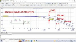
With a 150k load and 10-25pF load capacitance, you still have up to 2dB anomaly at 20 kHz given typical modern cart L and R. 150k R load and very low capacitance requires a very specific set of implementation conditions and knowledge of the cart L and R and actual load capacitance, much like difficulty MM phono stages that feed into summing junction type arrangement have in dealing with a wide range of carts.
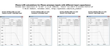
There is a reason the industry settled on 47k + 100-200pf: it gives the best overall response over a wide range of cart L and R. Below is the plot of Cload stepped from 50pF to 200 pF

There is a reason the industry settled on 47k + 100-200pf: it gives the best overall response over a wide range of cart L and R. Below is the plot of Cload stepped from 50pF to 200 pF
Last edited:
That is my detailed masterclass (see the last 10 minutes) about correct noise measurements of phono preamps (and know-how about how replacing a cheap resistor is better than paralleling 15-$ transistors):
This is not the place (between two red dots) where the Johnson noise curent generator is located. It should be in parallel with the 47k resistor as explained here.
With a 150k load and 10-25pF load capacitance, you still have up to 2dB anomaly at 20 kHz
I see only about 1 dB, which is a great result.
There is only one reason - to allow the user to connect the cartridge through the cable. If we exclude the cable, you can do much better matching.There is a reason the industry settled on 47k + 100-200pf: it gives the best overall response over a wide range of cart L and R.
This is what I used to think. However, I found that at least for some cartridges, C is needed to correct the FR of the mechanical system.There is only one reason - to allow the user to connect the cartridge through the cable.
The load of 150k is suitable only for those who do not have a cable at all, and the preamap is installed near the tonarm.Separately, how many people have a setup with 0 pF cable capacitance?
So far, no one has yet introduced real measurements of the test LP with the load of the cartridge 150K, where the correction is needed.However, I found that at least for some cartridges, C is needed to correct the FR of the mechanical system.
The whole point here is how many systems in the real world are like this? 0.5%? 1%? Who is going modify an expensive turntable like this? If you are a DIY guy with good skills, you might try it, but for most, they won’t take the risk. And high end commercial brands won’t do it because their customer base don’t want to be tied to a single phono amp solution.
The challenge surely should be ‘how do I create a SOTA preamplifier that can accommodate real world setups?’
Nicks design is full of implementation constraints that most people cannot meet. 0 pF cable capacitance, resistor cooling, ‘A’ weighting, special IEC measurement methodologies etc.
The challenge surely should be ‘how do I create a SOTA preamplifier that can accommodate real world setups?’
Nicks design is full of implementation constraints that most people cannot meet. 0 pF cable capacitance, resistor cooling, ‘A’ weighting, special IEC measurement methodologies etc.

Here are my measured frequency responses. Total capacitance from the cartridge to the preamp input is 100pF. I couldn't try 150k but tendency is clear when comparing 56k 0+100pF with 47k 220+100pF.So far, no one has yet introduced real measurements of the test LP with the load of the cartridge 150K, where the correction is needed.
The noise current generator of 47k resistor is located in parallel with 47k resistor, and noise voltage generator is located in series with 1k cartridge resistor. Don`t you know Thevenin/Norton + Kirchhoff ?This is not the place (between two red dots) where the Johnson noise curent generator is located. It should be in parallel with the 47k resistor as explained here.
See 150k + 25 pF for Lcart stepping = 250...1000 mH without any adjustment. That is 95% of MM carts. And that is a fact that you do not need any test disk and voltmeters/oscillo. Simply unscrew the 4 screws on the bottom panel of your turntable, solder 6 wires and screw the 4 screws back. Any DIYer can do it in 5 minutes, and ordinary housewife, after she finds out which end of the soldering iron is taken 😏, takes no more 15 minutesI said with a range of cart L and R typically found in the market, not just the .5H and 1k R you and Nick use
Attachments
Last edited:
You have conveniently omitted cart R in your sim. Additionally, your 150k load R means more noise necessitating additional complexity for resistor cooling, which under best case conditions is 2dB and a lot less with a JFET input.
- Home
- Source & Line
- Analogue Source
- Pros and cons: prime MM\MC phonopreamps "X-Altra" & "LP797" vs "Cy-XXI"