Are there any measurements that show a bad TIA result (MM cart) compared to a conventional amplifier?The problem is that the transimpedance approach, when you take everything into account you end up with something more complex than old fashioned voltage amplification.
I'd only meant the brute force approach as an example, but not as practical. It forms an integrator (for half a Henry and 10R the pole is about 3Hz) so would need to be differentiated later or some other modification to RIAA made, but not really useful in practice.If the zero input resistance is provided with a feedback, it will be a current-to-voltage converter. The frequency response will be the same as in the case of a low R load.
For a MM cartridge feeding a summing junction, its impedance and the feedback's impedance both determine output frequency response, so aren't really the same case as a brute force 10R load. Without the brute force load, and instead a TIA input, the response is exquisitely sensitive to the cartridge's impedance.
All good fortune,
Chris
We have - don't know how it happened but there's no problem discussing this stuff.Sorry thought we had meandered into just MM at the moment.
🙂
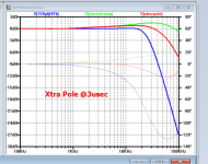
Have you read the paper I linked yesterday? We haven't built one yet, but Hans has shown theory matches measurements for the cartridge model. Attached shows AT150 generator. Blue line is voltage mode with optimal loading. Green is 'aurak' style transimpedance and red is the same with an additional pole to tame the rising response. This is the best candidate generator for transimpedance operation.Are there any measurements that show a bad TIA result (MM cart) compared to a conventional amplifier?
Attachments
You are wrong, you need to take not only 10R, but also the active resistance of the cartridge.for half a Henry and 10R the pole is about 3Hz
I tried the cartridge model from the article. I do not see any crime, with a transimedanced amplifier, a rise in 20 kHz is about 0.5 dB.Have you read the paper I linked yesterday? We haven't built one yet, but Hans has shown theory matches measurements for the cartridge model. Attached shows AT150 generator. Blue line is voltage mode with optimal loading. Green is 'aurak' style transimpedance and red is the same with an additional pole to tame the rising response. This is the best candidate generator for transimpedance operation.
Given that is where all the noise is and that 80% of records have no music signal much above 15kHz I don't view that as a good thing. But as I said before if you want to play go for it, just chose an AT or SuperOM as the base as most other cartridges are not as well behaved with this loading.
Aside: if you have CD4 recordings then the AT150 is a good cartridge for playing them as will pick up the HF carrier for about 300 hours until the diamond bottoms out.
Aside: if you have CD4 recordings then the AT150 is a good cartridge for playing them as will pick up the HF carrier for about 300 hours until the diamond bottoms out.
This affects the weighted noise weakly. Of course, you can add to the RIAA premp the adjustment "HF TRIM" in order to tune the frequency response on the test LP.Given that is where all the noise
Depends what you are looking for. I was of the opinion that razor flat to 20kHz was a good thing, but when you analyse recordings and realise that there is hash, grot and harmonics not on the original recording above 16kHz suddenly an early roll off seems a good idea for listening. But it's a matter of choice up to the choser rather than any physical absolute.
I'm just wondering if an LC network from cart output to GND couldn't be made to sim that resonance mode.

Rick is correct in his comment that the input impedance diminishes the S/N to above the specified 250pV/rtHz when using a 12R Cart.
Let’s have a look at the Spice model in Fig 1 to calculate the exact input impedance and the compound resistance of all resistances, 2*47K, 2*330K, 2*1K and both collector resistances, all being in parallel.
For that purpose the vital amp parts are entered in LTSpice, and a load resistor is selected for a gain of 20, see fig 2.

When looking for a gain of 20, the secondary resistance should thus be 20*3.75R = 75R.
After some trial, a value for Rload has to be 89.11R, also shown in Fig 1.
That means that all the above mentioned resistors in parallel are 89.11*75/(89.11_75) = 475R.
Translating the above schematic into a simpler replacement diagram, resulted in the circuit diagram in Fig 2, where the noise contribution of the transistors was entered as a parameter “En” in the Op-Amp.
When shorting the input to gnd, a noise value RTI of 214pV/rtHz will be found, well below the speciufied 250pV/rtHz.

As a next step, I have placed the 12R cart that Nick mentioned to have in the simulation.
Here the Gain was to 10, because noise performance is slightly worse at a lower gain, but for a head amp, this will be the minimum Gain that will be ever needed.
The input impedance is now 12R +3.75R = 15.75R
For a gain of 10, the secondary side will have to be 157.5R, resulting in a Rload of 235.6 in parallel to the previous calculated fixed value of 475R.
Simulating this, results in a noise RTI figure of 522pV/rtHz, see Fig 2.
The Cart’s 12R resistor produces 447pV/rtHz.
Ergo, the X-Altra’s noise contribution is Sqrt(522^2-447^2) = 269pV/rtHz RTI, above the specified 250pV/rtHz and 2dB more noise contribution as with the input shorted.
Hans
Let’s have a look at the Spice model in Fig 1 to calculate the exact input impedance and the compound resistance of all resistances, 2*47K, 2*330K, 2*1K and both collector resistances, all being in parallel.
For that purpose the vital amp parts are entered in LTSpice, and a load resistor is selected for a gain of 20, see fig 2.
Fig 1, LTSpice model used to find the load resistor for a gain of 20.
The calculated input resistance of 3.75R in the left part of the image, corresponds perfectly with the measured input resistance in the right part of Fig 1.
When looking for a gain of 20, the secondary resistance should thus be 20*3.75R = 75R.
After some trial, a value for Rload has to be 89.11R, also shown in Fig 1.
That means that all the above mentioned resistors in parallel are 89.11*75/(89.11_75) = 475R.
Translating the above schematic into a simpler replacement diagram, resulted in the circuit diagram in Fig 2, where the noise contribution of the transistors was entered as a parameter “En” in the Op-Amp.
When shorting the input to gnd, a noise value RTI of 214pV/rtHz will be found, well below the speciufied 250pV/rtHz.
Fig 2, Replacement diagram for X-Altra
As a next step, I have placed the 12R cart that Nick mentioned to have in the simulation.
Here the Gain was to 10, because noise performance is slightly worse at a lower gain, but for a head amp, this will be the minimum Gain that will be ever needed.
The input impedance is now 12R +3.75R = 15.75R
For a gain of 10, the secondary side will have to be 157.5R, resulting in a Rload of 235.6 in parallel to the previous calculated fixed value of 475R.
Simulating this, results in a noise RTI figure of 522pV/rtHz, see Fig 2.
The Cart’s 12R resistor produces 447pV/rtHz.
Ergo, the X-Altra’s noise contribution is Sqrt(522^2-447^2) = 269pV/rtHz RTI, above the specified 250pV/rtHz and 2dB more noise contribution as with the input shorted.
Hans
Attachments
Nick claimed 1.26 nV/rt Hz and not 522 pV/rt Hz With 12 Ohms
If you connect a higher Rcart, noise will go up and it will be dominated by the cart thermal noise. But the noise contribution from the X-Altra input stage will not change IMV.
You are claiming an additional 19 pV/rt Hz above the spec of 250 pV/rt Hz. I will take a look at it in the morning, but I’m not going to lose any sleep over it if it’s below the measurement capability.
- Home
- Source & Line
- Analogue Source
- Pros and cons: prime MM\MC phonopreamps "X-Altra" & "LP797" vs "Cy-XXI"