I just checked, the lower source R measurement was done with the input shorted. With 47 Ohms Rsource the spot noise floor I measured was -124 dBV (vs calculated -124.4 dBV) and with the input shorted -112 dBV vs -113 dBV calculated. As remarked in the write up, the spot noise was visually determined from the display, so there is some visual uncertainty because of display 'grass' (maybe 0.5~1 dB)
The measurement technique and calculation is detailed in the X-Altra MC/MM download pack on www.audioXpress.com here https://audioxpress.com/files/attachment/2737
The measurement technique and calculation is detailed in the X-Altra MC/MM download pack on www.audioXpress.com here https://audioxpress.com/files/attachment/2737

Surely there's a way to bootstrap the transistor with an opamp to get zero input impedance if you want it? You can for high input impedance.The MC input of the X-Altra is responding to current, so you have to consider the cart as a voltage source (with an internal R) being shunted by 3.5 Ohms - ideally you want it to be 0 Ohms, but you only get that with opamp based designs and that comes with a noise penalty.
Mark, the actual input is within 0V to worst case few tens of uV and nominally below 10uV - the DC servo sees to that. However, the internal emitter resistances of the input transistors mean that to AC sources with the servo engaged, they see c. 3.5 Ohms and not 0 Ohms (without the servo, the AC input impedance is double that at 7 Ohms). If you use a good quality, low noise opamp like an AD797 or OPA1612 you will get 0 Ohms input impedance - so it's pretty much a real current input configuration. But, as mentioned earlier, these approaches are 10-12 B worse in terms of noise compared to the transimpedance solution. The non-zero input impedance only becomes apparent at very low source resistances - so << 10 Ohms. Even then, the transimpedance stage is still quieter than an opamp approach. The challenge with bootstrapping to get close to 0 ohms input impedance is how do you get rid of the opamp noise contribution without too much additional complexity.
You could of course take a different approach here and run the transistors at much higher collector current to lower the noise and reduce re', or even parallel them, and the result will be lower noise and lower input impedance. But that will require matching/selection and what real benefit will that bring given vinyl surface noise is 15 dB higher than a good phono amplifier noise? I think there is a performance/complexity/cost tradeoff to be made here and Leach got it spot on - for just two low-noise transistors and a few passives you get SOTA performance. Hopefully, the X-Altra MC/MM delivers on that score.
Getting 0 Ohms input impedance with a discrete transimpedance stage maybe something for a younger, more agile brain than mine to look into 🙂
Professor Leach wrote a book on noise in electronics. He used to allow his students to download, but decided to publish and stopped that. I have no idea what the copyright status is on this.
https://www.pearl-hifi.com/06_Lit_Archive/07_Misc_Downloads/030_Noise_by_Marshall_Leach.pdf
https://www.pearl-hifi.com/06_Lit_Archive/07_Misc_Downloads/030_Noise_by_Marshall_Leach.pdf
Your calculation of noise using the voltage divider approach is not correct
it is not mine but Micrcocap sumulation ("inoise" function of AC Analysis - page 218 of https://www.iee.et.tu-dresden.de/~jmueller/simulation/soft/microcap/MC12.RefManual.pdf ). Microcap measures the contribution from all of noise sources and makes it better of all. All you said belongs to the emitter point as input, but cartridge has input not at emitters but at its EMF. And it is an Rsource between EMF and emitters. When we need a true SNR ref. EMF=0.4 mV, we must use EMF point and recalculate noise to it, not emitters. Or if you want, you must delete input EMF by Rin/(Rin+Rsource) and than use noise RTI with (or at) emitters as input point.
Last edited:
I use for Microcap sumulation MC preamp circiut published in AXpress Feb 2021 page 64. I only add @ input Rsource=3 Ohms and Lsource=75 uH as typical for MC cartridge (as mine Benz Micro Glider M2), because "input shorted" condition is not a real, particularly for noise definitions.is it last one? With or wo input defender?
Nick,
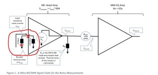
on the X-Atra MC/MM MC input, the input is responding not to voltage but to current. You have to convert any source resistance thermal noise voltage to an equivalent noise current and then do the calculations. The equivalent thermal noise contribution of the MC input stage was calculated, simulated with LTspice and then measured and the result is <250pV/rt Hz RTI contribution from the amplifier. As I explained in the document below, to verify the equivalent thermal input noise, the measurements were done at two extremes - one with Rsource = 47 Ohms and the other with the input shorted so Rsource = 3.5 Ohms (this is 0.5*re'= 0.025/Ie). Since the MC stage gain is dependent upon Rsource, by taking this into account, the measurements accurately reflect the total signal chain gain and thus output measured noise. This allows the measured output noise to be accurately referred to input (RTI).
With a transimpedance input like the X-Altra, you have to model Rsource as a voltage generator in series with coil resistance, not just a voltage source.
Please see the document below for how I did it. For low Rsource generators like MC cartridges, there isn't any lower noise circuit than the transimpedance stage. You can use JFET's, but then you have to parallel many of them (with attendant instability problems - see Scott Wurcer et al on this forum) to get anywhere near <250 pV/rt Hz. Opamps work well, but the best available types are 10 dB more noisy; diff input bipolar stages are 6-9 dB more noisy. The Leach circuit remains the best bang for buck for MC inputs.
Attachments
Last edited:
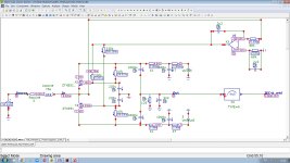
Andrew, of course I have model MC cartridge as a voltage generator V1 in series with coil resistance Rsource and coil inductance Lsource [ https://www.diyaudio.com/community/attachments/ztx_russell_cir-jpg.1204711/ ]. You can download my circuit file here [ https://www.patreon.com/posts/detalno-endriu-o-88013121 ] and make a detailed simulation in Micrcocap 12. Or simply see my video:
The gain of the MC front end is related to the source resistance ie AV ~= Rload/Rsource where Rload is the collector load resistance of input transistors. So, if you step Rsource and look at Vinoise vs. Vonoise you will indeed see a large discrepancy and that's because of the big differences in gain. Note that on the X-Altra MC/MM, Rload is switchable so you can adjust the MC gain to match the cartridge being used.
If you look at the doc I posted above, you will see that the discrepancy in gain for 3.5 Ohm vs. 47 Ohm Rin is c. 619x vs. 9576x - so Vonoise is much higher with 3.5 Ohms Rsource. However, in all cases, if you calculate the noise RTI, its ~250 pV/rt Hz. If you look at the doc I posted above, you will see that the discrepancy in gain for 3.5 Ohm and 47 Ohm Rin is c. 619x vs 9576x - so Vonoise is much higher with 3.5 Ohms Rsource.
I only use Vonoise when working with power supplies since Vionoise really doesn't mean anything. For amplifiers, it's more instructive IMV to look at just Vinoise (from which spot noise or SNR ref the input signal can easily be calculated) for the very reasons stated above. If you are going to use Vonoise, you will have to calculate the SNR wrt the expected output level
Inoise is calculated across the same output nodes as Onoise, but is divided by the gain from the input source to the output node, and therefore does not depend on the gain. Your mistake is that a common point of 47 ohms and 3.25 ohms (or ZTX emitters) is accepted under the input node, while metrologically it is correct to consider the ground output of 47 ohms or cartridge emf under the input node. With correct input node RTI of ZTX851\951 with Rbb=1.2/1.5 OHms are 217 pV\rt Hz with shorted input (unreal condition), 538 pV\rt Hz with Rsource=12 Ohms and 1.141 nV\rt Hz with Rsource=47 Ohms.
Attachments
I don’t understand what you are trying to claim here.
Why don’t you tell me what you think the RTI noise spec of the X-Altra MC/MM is and how that gels with the measured noise then maybe I can unravel your concerns.
Why don’t you tell me what you think the RTI noise spec of the X-Altra MC/MM is and how that gels with the measured noise then maybe I can unravel your concerns.
Last edited:
Nick, I’m not paying to look at stuff you’re posting on Patreon about my circuit.
If you think the X-Altra MC measured, simmed and calculated noise spec is wrong, tell us what it is and why.
(The noise calc doc drawing is s conceptual overview of the measurement approach - it is not meant to be a precise input circuit representation).
If you think the X-Altra MC measured, simmed and calculated noise spec is wrong, tell us what it is and why.
(The noise calc doc drawing is s conceptual overview of the measurement approach - it is not meant to be a precise input circuit representation).
‘With correct input node RTI of ZTX851\951 with Rbb=1.2/1.5 OHms are 217 pV\rt Hz with shorted input (unreal condition), 538 pV\rt Hz with Rsource=12 Ohms and 1.141 nV\rt Hz with Rsource=47 Ohms.’
You have included the source resistance noise. Rsource will always have thermal noise. This does not tell you what the amplifier noise is. It remains at c. 250 pV/rt Hz no matter what Rsource is. No one is arguing that higher Rsource will result in higher generator thermal noise but it tells nothing of the amplifier only noise contribution.
This is precisely why the output noise was measured at 2 different Rsource values. Both of those measurements support a spot noise contribution from the amplifier only of c.250 pV/rt Hz. If you use a high Rsource cart, all other things being equal, the system S/N will be worse because of the cart thermal noise contribution.
Do you understand why the measurement was done with 47 ohms Rsource and then with the input shorted?
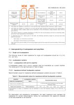
The thermal noise of the cartridge is in the background for your version of complementary ZTX851/951, because in the foreground is the low input impedance of the common base with a collector current of 3.5 mA, this is 30 times more than that of the Marshall-Leach 0.125 mA (and produce 200/2=100 Ohms input impedance). And keep in mind that table 8 of IEC standard IEC-61938:2018 requires an input impedance of not less than 100 ohms for MC preamplifiers - see attach, as most of MC cartridge makers require [ https://www.audio-technica.com/en-us/at-f3iii - see Specifications] .
(with multilanguage subtitles)
Can I get a LTSpice file of your MC preamp circuit to find a mistake?
Can I get a LTSpice file of your MC preamp circuit to find a mistake?
Attachments
Last edited:
I’ve given you the sim file, the measurements are in the public domain and are consistent with those of similar designs so I am at a loss as how to explain anything further to you.
The input is current sensitive and when you feed a MC into a virtual earth (or close to it), it behaves like a current transducer. And that’s exactly why low R carts (which produce HIGH output currents) into a TIS (aka ‘current injection’) offer such great noise performance.
Be aware there are a few commercial designs using TIS input stages that are also highly regarded - see Stereophile etc. - so this is not some DIY hack type approach. Marshal Leach was a PhD electronics engineer and well respected academically.
But, as I wrote earlier, you will have to explain away the noise measurements that show very close to the predicted sims and calculations, both of which confirm an amplifier noise contribution of 250 pV/rt Hz.
I explained in the audioXpress article that the c 3.5 mA collected current used was done as a trade off between power consumption and noise. Higher Ic would bring a bit lower noise but a more complex PSU rather than the LM4562 approach used.
I suspect this is as much about you trying to defend your design in the face of a topology that clearly offers superior noise performance on MC.
What do you think the 1kHz spot noise is on the X-Altra MC/MM?
Integrated noise 20-20kHz?
What is the S/N ref 200uV and 10 Ohms generator?
Integrated noise 20-20kHz?
What is the S/N ref 200uV and 10 Ohms generator?
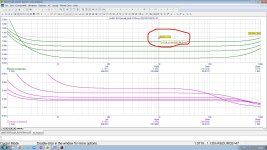
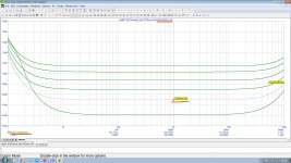
495 pV/rt Hz , Integrated noise @20kHz 495x141=69.8 nV, SNR ref 200 uV 200000/69.8=2865 = 69.1 dB - my simulation @ Microcap 12. Run AC Analysis and see Inoise @ Rsource=10.What do you think the 1kHz spot noise is on the X-Altra MC/MM?
Integrated noise 20-20kHz?
What is the S/N ref 200uV and 10 Ohms generator?
Circuit file with .cir extension is not allowed as attaches at this forum, therefore is here: https://www.patreon.com/posts/ztx851-951-po-ms-88618453 . Free Microcap 12 installer is here: https://www.patreon.com/posts/podstrakhoval-12-84096514
Attachments
- Home
- Source & Line
- Analogue Source
- Pros and cons: prime MM\MC phonopreamps "X-Altra" & "LP797" vs "Cy-XXI"