Here is the noise calculation for the X-Altra MC/MM MC input stage (bottom graphic)
The amplifier noise contribution only (so NOT THAT OF THE GENERATOR RESISTANCE) is specified at 250 pV/rt Hz. The measured spot noise was 232 pV/rt Hz. This figure comprises the thermal noise contribution of the input devices rbb’ and the power supply noise at 50 pV/rt Hz.
It does not matter whether Rsource is 10 Ohms or 30 Ohms. The amplifier noise contribution will by and large remain at the specified figure of 250 pV/rt Hz. Any noise above this figure is that of the generator resistance.
To verify the noise performance of the amplifier (this is the whole signal chain noise from MC input to the output of the preamp) the noise was calculated with input shorted. This would then give only the amplifier noise once the gain was accounted for. The gain was then calculated with an input resistance of 47 Ohms. By looking at the input extremes, the amplifier noise contribution could be verified at two points ie a robust result. The measured figures were out by 0.4 dB with 47 Ohms Rsource ie -124 dBV vs -124.4 dBV calculated and simmed, and with the input shorted and a calculated Rsource of 3.5 Ohms, -112 dBV vs -113 dBV.
Also attached is a table that allows you to read off the total amplifier noise if you know the equivalent thermal noise resistance of just the amplifier and then your source resistance only.
The X-Altra MC/MM performance places it along the top row. Forgive the trumpet blowing, but this is pretty much SOTA in terms of noise. Kudos for this of course should go to Marshal Leach for his complementary common base design insight and I’d add Richard Lee to that as well 👍🏻
Last edited:
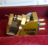
10 Ohms, as you asked "What is the S/N ref 200uV and 10 Ohms generator?". But for MC I prefer use 12 Ohms as in my favorite Benz Micro Glider M2What Rsource did you use?
Attachments
To verify the noise performance of the amplifier (this is the whole signal chain noise from MC input to the output of the preamp)
The whole signal chain must include source resistance and inductance.
the noise was calculated with input shorted. This would then give only the amplifier noise once the gain was accounted for. The gain was then calculated with an input resistance of 47 Ohms.
The gain from MC cartridge EMF to output of MC preamp include both divider Rin/(Rsource+Rin) and naked preamp amplification from bases 851\951 to output. If Rsource = 47 and Rin=3.5 you must decrease signal level before bases of ZTX851\951 by (3.5 + 47)/3.5=14.43 or 23.2 dB. Or equally increase noise by 23.2 dB (RTI noise with input node at MC cart EMF, not at ZTX bases).
Nick, I’ve told you the measurement doc is not an actual circuit but simply a drawing showing the points in the circuit where the voltages were computed. The 3.5 ohm input impedance is in series with the source resistance therefore there is no ‘divider action’. The input stage is responding to current, and NOT voltage.
The thermal noise from your Benz cart is nearly 4x that of the X-Altra MC input stage. And if you use a DL103 like I have, the cart generator resistance is contributing 10x what the X-Altra MC stage is.
The thermal noise from your Benz cart is nearly 4x that of the X-Altra MC input stage. And if you use a DL103 like I have, the cart generator resistance is contributing 10x what the X-Altra MC stage is.
This is the noise of the X-Altra MC input stage only. The generator resistance has been set to 0. This figure does not include the PSU noise used in the actual design of 50 pV/rt Hz. The noise contribution from the servo is essentially zero


This now is the noise with Rg (the cartridge generator resistance) stepped from 3.5 to 35 Ohms - ie the short shown across rg in the previous post is removed). All of the spot noise above c. 250 pV/rt Hz is from the cartridge generator resistance. So, the lower the cartridge generator resistance (and the higher the output current), the better the performance. Again, since this is a transimpedance amplifier (aka 'current injection'), the input is responding to current, not voltage.
The inductance of 75uH makes essentially no difference to the X-Altra MC amplifier noise performance over 20Hz to 20 kHz (this of course is not the case with MM where the very high inductances have to be considered)).

The inductance of 75uH makes essentially no difference to the X-Altra MC amplifier noise performance over 20Hz to 20 kHz (this of course is not the case with MM where the very high inductances have to be considered)).
Last edited:
Nick, here is the full chain sim using a 12 Ohm 200uV Benz cartridge. The stage gains are set to give c. 1V output (4mV at the MC output, 140mV out of the MM EQ stage and then the system gain stage set to raise the gain to give 1V output).
To calculate your S/N, I used Vonoise because we want to include the noise shaping that the RIAA EQ stage is providing.

Here is the Vonoise plot with the total integrated noise 20Hz - 20 kHz

So reference the 1V output of the whole signal chain (this excludes any A weighting), the signal to noise ratio using a Benz 12 ohm cartridge is 70.44 dB. With A weighting, it will be about 4 dB better.
You can of course play with the stage gains a bit to further optimise the S/N in which case you can squeeze another 1-2 dB (my guess) out of the system.
To calculate your S/N, I used Vonoise because we want to include the noise shaping that the RIAA EQ stage is providing.
Here is the Vonoise plot with the total integrated noise 20Hz - 20 kHz
So reference the 1V output of the whole signal chain (this excludes any A weighting), the signal to noise ratio using a Benz 12 ohm cartridge is 70.44 dB. With A weighting, it will be about 4 dB better.
You can of course play with the stage gains a bit to further optimise the S/N in which case you can squeeze another 1-2 dB (my guess) out of the system.
If Nick thinks this is noisy he won't like my Burning Amp 2023 phono stage at all.
This is a well done phono with SOA parts. Cartridge, arm and cable noise will dominate.
This is a well done phono with SOA parts. Cartridge, arm and cable noise will dominate.
I agree that 71 dB. And what about RTI noise? -71 dB ref. 1 V output is 0.28 mV (at output) and 0.178 uV or 178 nV RMS ref. MC head EMF source (V4 AC1 in your circuit, not ZTX emitters, right ?). It is equal to 1.26 nV/rt Hz, not 250 pV/rt Hz as you declare. PS. 12 Ohms resistor generate itself only 0.44 nV/rt Hz or 62 nV RMS @ 20 kHz BW (and therefore 1.26 nV/rt Hz due to preamp - not 12 Ohm resistor).the signal to noise ratio using a Benz 12 ohm cartridge is 70.44 dB
Last edited:
Wayne, I am sorry I haven't seen your preamp circuit diagram and I haven't heard him playing LP. My Cy-XXI phono preamp you can hear here [ https://www.patreon.com/posts/proslushka-cy-v-89311755 ] and see circuit and detailed desription here [ https://www.patreon.com/posts/skhema-gerbery-i-86997687 ] DIY KIT is available for $100 here: [ https://imrad.com.ua/ua/fonokorekto...vok-zvukoznimacha-z-ruhomim-magnitom-mm-50389 ]he won't like my Burning Amp 2023 phono stage
Attachments
Last edited:
I agree that 71 dB. And what about RTI noise? -71 dB ref. 1 V output is 0.28 mV (at output) and 0.178 uV or 178 nV RMS ref. MC head EMF source (V4 AC1 in your circuit, not ZTX emitters, right ?). It is equal to 1.26 nV/rt Hz, not 250 pV/rt Hz as you declare. PS. 12 Ohms resistor generate itself only 0.44 nV/rt Hz or 62 nV RMS @ 20 kHz BW (and therefore 1.26 nV/rt Hz due to preamp - not 12 Ohm resistor).
You are confusing the measurement doc, the sim, and the actual measurements. They are three separate things designed to work together to ensure a robust underpinning of the noise performance claimed in the spec.
1. The measurement doc shows 3.5 ohms because that is the equivalent input noise resistance with the input shorted. It is just a model. I used that model to calculate to total RTI spot noise.
2. If you then run a sim with the actual circuit you do not have to talk about this resistor because it is taken care of by the device models and will get about 200 pV/rt Hz spot noise RTI. So the sim circuit does not need to show this resistor
3. Then if you MEASURE THE PREAMPLIFIER with a QA401 you get 232 pV/rt Hz RTI spot noise. The measured preamplifier spot noise will include some PSU noise plus noise from the TIS load resistor and the MM stage - the total RTI contribution is a few low 10's pV/rt Hz.
Once the spot noise is confirmed with the above 3 step procedure, the 1 kHz spot noise RTI is confirmed and specified 250 pV/rt Hz. Anything greater than this is attributable to the cart thermal noise.
For total integrated noise, you have to consider the RIAA noise shaping - the RTI or RTO thing does not change the fundamental measurement results because the LTspice sim will take the system gain vs frequency into account. In my calculation of your S/N using the Benz cart, I simply went through the complete process to show how it would be set up in practice.
In the measurement doc, I explain why I calculated spot noise and not total integrated noise. If I calculated total integrated noise, I would have to split the audio band up into sections and calculate the noise for each band and then RMS sum the individual band noises because of the RIAA response shaping.
You have to consider the cartridge as a voltage source in series with the cart resistance. The total input noise with a cart connected will be the cart resistance plus the input equivalent thermal resistance of the preamp of c. 3.5 ohms. The two add RMS style for the total equivalent input thermal noise - it’s clear that if the cart resistance is 3 or 4 x the thermal resistance of the input then the cart noise will dominate.Andrew, see english subtitles
It is not correct to treat the 3.5 ohm input resistance and the generator resistance as a divider. The two resistances must be added in series to determine the input current - this is discussed in the audioXpress article. The X-Altra is a current injection aka transimpedance amplifier.
I calculated the equivalent input noise by first converting it to a current in the noise calculation doc. Once the thermal noise is confirmed, then we can just use it to work out the S/N with any cart. The S/N will be worse with higher R carts for a given output voltage.
Please study the circuit, sim and noise calculation methodology before making claims in your video that are unfortunately not correct.
Last edited:
Nick, Here is a comparison between the Self circuit you discuss in your video and the X-Altra. Self is very well respected audio designer with over 40 years industry experience and has published some very good books. His MC phono stage is state of the art with excellent specifications and is an interesting approach to low noise MC amplifier design. However, it is not quite as good as the Leach current injection circuit used in the X-Altra MC - see noise curves below.
You could parallel another set of transistors with the X-Altra circuit and get the front end stage noise down to about <200 pV/rt Hz. However, as in the Self design, the transistor Vbe's would have to be matched as there would be serious current hogging and that would have a negative effect on noise in that the noise would be higher than that predicted with matched devices. Modelling won't show that unless you specifically include those parameters in your analysis.
I looked at your analysis of the X-Altra in your video and the reason you got >1.1 nV/rt Hz vs half that for the Self stage is you had a 3.5 Ohm resistor from the input to ground on your X-Altra model. Please see the graphic below for the correct model. There is no 3.5 Ohm resistor to ground in the actual circuit. The impedance looking into the junction of the two emitters with the servo attached is around 3.5 Ohms (ideally we want it to be 0 Ohms) but that is not the same as 3.5 Ohm resistor to ground. The equivalent noise voltage is also about 3.5 Ohms and exclusively due to rbb' plus PSU noise plus MM amplifier RTI noise. re' does not play a significant role in noise in a common base amplifier and this was the major insight from Marshal Leach. To visualize this, imagine an opamp configured as a current input inverting amplifier so Vo = Iin*Rf where Iin is the cartridge output current from Vo/Rcart. In an opamp circuit, the Zin will be very close to 0 Ohms because the summing junction will be at 0V and the feedback will be high. To understand how the X-Altra MC looks, add a 3.5 Ohm resistor in series with the opamp input with the other end to the cartridge - note it is not connected to ground but in series with the input source resistance.
In the noise analysis I did on the calculation doc with the input shorted, I put a 3.5 Ohm resistor to ground to represent the noise - 3.5 Ohms to ground does not exist in the real world circuit. All of the current coming out of the cartridge flows into the respective collector load in the X-Altra MC (base current errors notwithstanding) and that current is the cartridge output voltage divided by the [cartridge resistance + the input resistance of 3.5 Ohms]. There is no voltage divider action.
In the model below, both inputs are at 200uV and generator resistance is 12 Ohms.
Last edited:
Hi, yes, he covers a few in his 'Small Signal Audio Design' book (Chapter 8) - I have not seen the Wireless World article. John Curl's MC head amp is similar to Figure 8(c) but IIRC he placed feedback around it - there's a sim of it in the MC Head amp compendium here https://hifisonix.com/wp-content/uploads/2019/08/Moving-coil-head-amps-rev-2.pdf
The Leach configuration dates from 1977/8 IIRC.
The Leach configuration dates from 1977/8 IIRC.
There are publications where the frequency response graphs for the MC cartridges with different load resistance are given. Deviations from linearity can be very large. I do not know whether this is true, because I have little experience with the MC cartridges. The reason for the fall of the level after 2 kHz at low load resistance is not entirely clear. The L/R constant for MC cartridges usually has small value, the cut-off frequency is outside the sound range (for some cartridges, the cut-off frequency can be close to the upper edge of the sound range, giving a noticeable drop in the level of 20 kHz). Maybe the losses are growing noticeably with an increase in frequency, changing impedance?

If you have a voltage input stage with a low value resistive load (say 33 or 50mohms for example) I would expect there to be some divider action plus the effects of cart L at HF. On current injection input circuits you are really looking at the cart output current into a short circuit, so there is no divider action from the cart resistance and the input resistance although there will be some small response effect at HF due to cart L. Provided the cart resistance is reasonably flat with frequency, the output current should be flat.
I‘m using a DL103 BTW.
I‘m using a DL103 BTW.
- Home
- Source & Line
- Analogue Source
- Pros and cons: prime MM\MC phonopreamps "X-Altra" & "LP797" vs "Cy-XXI"


