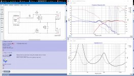
After further listening I changed the Tweeter polarity back. While that improved somethings it made S's in Voice and certain cymbal sounds and other artifacts rather harsh. Oh well trail and ERROR LMAO
This really does take time to sort out and improve. I have a whole menu of known songs to play with these changes and make mental notes. I need to understand more about the phase lines and what my target is for those.???
This really does take time to sort out and improve. I have a whole menu of known songs to play with these changes and make mental notes. I need to understand more about the phase lines and what my target is for those.???
You have them within 90 degrees and moving together through the crossover region. This is a good start.
As you get closer the game changes. There is not going to be a perfect unless your acoustic design allows it, and it will take a long time to find it.
As you get closer the game changes. There is not going to be a perfect unless your acoustic design allows it, and it will take a long time to find it.
Started Over
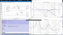
I re read your excellent Crossover Design Sticky and went back to the drawing board and started over. I was not really even understanding nor paying attention to system impedance. So starting from the beginning with the proper step of flattening the impedance in each driver and also placing some resistors in my paths around inductor and caps so I have more control. This is already much better. I will work on this a while before trhrowing up anymore pics. I need to know though what general rules should I apply as my goal for sustem impedance? I am in a flattish channel now between 2.43 ohms and 4 ohms!
I re read your excellent Crossover Design Sticky and went back to the drawing board and started over. I was not really even understanding nor paying attention to system impedance. So starting from the beginning with the proper step of flattening the impedance in each driver and also placing some resistors in my paths around inductor and caps so I have more control. This is already much better. I will work on this a while before trhrowing up anymore pics. I need to know though what general rules should I apply as my goal for sustem impedance? I am in a flattish channel now between 2.43 ohms and 4 ohms!
Allen B how do I sharpen the tweeter knee and raise the crossover point at the same time. My crossoover when I get it nice looking is slightly to low in the 1743hz transfer region. I think I need to be at or above 2K really 2.2K???
If you can work with it better when you flatten impedance, we can wait until you have a good result and undo this without changing anything to increase your impedance.
Reduce the inductor value.Allen B how do I sharpen the tweeter knee and raise the crossover point at the same time.
You're getting somewhere, but before getting too pedantic I'm wondering about R1, R2 and C1. Also what delay have you used?
R1 R2 & C1 are the impedance flattening components I got from your crossover tutorial. Are those not to be actually used in the circuit. Not sure what you mean by delay. You do realize this is just a crossover in the app not one I have put in and measured?
Yes I realise, but I see something with your phase. As I cannot see your *.dxo file, I am asking you for the reason.
Don't put components directly across the amp. The impedance flattening components go between the crossover and the driver.
Don't put components directly across the amp. The impedance flattening components go between the crossover and the driver.
My bad on the impedance circuits. I moved those.
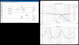
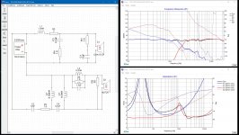
Ok I think this is better. I moved the impedance matching to the correct place...maybe...lol
I got the freq fairly flat. I got the woofer knee down. I lowered the tweeter. I turned the upper freq down on the high end with the contour circuit (I thinks that what that is L4 R6 C5) without that section the upper freq goes up at a hard angle somewhere after 5.5k to 6k. Am I getting a little closer now? These circuits are just so interactive...change one thing and you have to change a lot of others.
Attachments
Until that, and proper measurements are done there is only so far you can go without wasting your efforts on refinement.
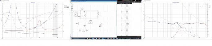
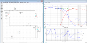
I removed the woofer resistor, it wasn't really helpful in this case. Consider your box. It isn't included yet but it is going to increase the bass a little so the fall below 150Hz can probably be ignored at this point.
The basics can be achieved with far fewer components. If you want to iron out the specific bumps and dips you can add many components, but best done when the data is equally specific.
Attachments
Thank you Sir
Thank you very much for taking time to help with this. This is going to be great since I have the custom center box that is so very close to my towers. I also learned more when I saw your drivers had that aqua colored H. I was able to switch to derived and now I understand more about your questions to me and it clears up all those nasty confusing phase anomalies.. I've built a lot of active electronics and tube gear. I even made a complete power tube board for the Peavey Classic 50 with individual bias controls and lots of goodies I learned from Kevin O'Connor. Saying that because I will make a crossover board that has room to grow and looks professional.
Thank you very much for taking time to help with this. This is going to be great since I have the custom center box that is so very close to my towers. I also learned more when I saw your drivers had that aqua colored H. I was able to switch to derived and now I understand more about your questions to me and it clears up all those nasty confusing phase anomalies.. I've built a lot of active electronics and tube gear. I even made a complete power tube board for the Peavey Classic 50 with individual bias controls and lots of goodies I learned from Kevin O'Connor. Saying that because I will make a crossover board that has room to grow and looks professional.
Rethinking for now I will just hack up this existing board and use the 3 4.0uf stacked with a 1.5 added for the 13.5uf. That will be more economic for a test board. And I have some turret stuff from Tube boards I built so maybe with a little think through I can hack a decent test board out of what I have and save on component costs.
- Home
- Loudspeakers
- Multi-Way
- Project Polk T50