Safer and future friendlier is to attach photos directly to this forum so anyone interested could see it. It is easy to do so.
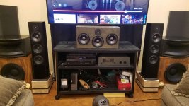
Ok reviving this thread as I move forward. I became very stalled trying to understand and use the various crossover and speaker simulation applications. I knew I needed to learn more and also be able to ask more relevant questions. I have since posting last here built my 1st 2 way speaker enclosure and did so to match my towers. I just finished the center and will add pics here in a minute. the enclosure is much taller than most of you would put up with but I designed it based off of much reading and the desire to match as closely as possible the towers it goes with. My enclosure meets the golden ratio rules. It is also passive radiators x2 just like the towers and indeed uses the same drivers and crossovers. I have spent a good bit of time dialing it and the overall system in as regards to distance, levels, and EQ within my AVR. It is extremely enjoyable and I now have a system that allows for voices and center channel content to have vastly improved clarity, loudness and dynamics.
I've been reading (https://www.diyaudio.com/forums/members/allenb.html) crossover sticky. I have immersed myself into PCD8. I have questions losts of questions. I have a goal of taking this to the next level. I feel it can be better I know something is missing, but I can't place my finger on it. After making several crossovers in PCD8 some common things came to light and even helped me in getting a better EQ curve. I'm ready to take the next step and make a proper crossover. I have the EMM6 and Presonus Firebox for room measurements. I have the DATS V3 for speaker and enclosure measurements. I have worked up 3 crossovers but I am not sure which path to take or how to improve these further or if the ones I made so far are even any good at all. I do intend to reverse polarity physically on the existing setup with regards to the tweeters just because in the PCD8 it seems to solve a peak issue at 4787hz no matter how I simulate the crossover. gather pics and info on where Im at shortly. Thank you.
I've been reading (https://www.diyaudio.com/forums/members/allenb.html) crossover sticky. I have immersed myself into PCD8. I have questions losts of questions. I have a goal of taking this to the next level. I feel it can be better I know something is missing, but I can't place my finger on it. After making several crossovers in PCD8 some common things came to light and even helped me in getting a better EQ curve. I'm ready to take the next step and make a proper crossover. I have the EMM6 and Presonus Firebox for room measurements. I have the DATS V3 for speaker and enclosure measurements. I have worked up 3 crossovers but I am not sure which path to take or how to improve these further or if the ones I made so far are even any good at all. I do intend to reverse polarity physically on the existing setup with regards to the tweeters just because in the PCD8 it seems to solve a peak issue at 4787hz no matter how I simulate the crossover. gather pics and info on where Im at shortly. Thank you.
Driver files
These are my drivers>
These are my drivers>
Attachments
Last edited:
My PCD8 attempts thus far
These 3 files are my 1st attempt at building crossovers in PCD8. I most likely have lots of faults, but it sure was fun tweaking and getting to this point.
The 2nd order and 3rd order were before reading AllenB's excellent crossover writeup. The 3rd attempt I attempted to apply some impedance matching on the woofer. I have a nasty little spike at 4787 and in the first 3rd orderish attempt reversing the tweeter polarity seemed to help a lot. I use the term "orderish" because after reading more I see that what you end up with may be a combination or hybrid of different "textbook" filters. It all depends on your drivers.
Attachments
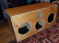
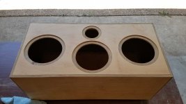
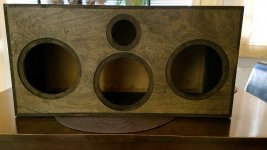
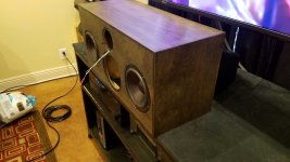
My 1st Center Channel from scratch!
As I stated before this is most likely way to big for most tastes and maybe even totally wrong. But it's kinda purty and sounds good...and well its made from some 9ply void free marine grade uber nice plywood with heavy MDF bracing.
As I stated before this is most likely way to big for most tastes and maybe even totally wrong. But it's kinda purty and sounds good...and well its made from some 9ply void free marine grade uber nice plywood with heavy MDF bracing.
Attachments
It would be interesting to look at these. It is excellent that you have learned a crossover simulator, but PCD is not working for me. Can you show your circuits and post your offsets..
Crossover Software
Yes Sir will upload shortly. If PCD is not good for you then what is and do I have to buy it? Lol.
Yes Sir will upload shortly. If PCD is not good for you then what is and do I have to buy it? Lol.
Please continue with PCD. I simply cannot see your circuit. A screenshot, drawing or description will do.
Images from PCD
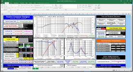
Is this useful or is there a better way to share this info?
I like this one the best so far. But that is based only on making the most flat frq response so far.
Is this useful or is there a better way to share this info?
I like this one the best so far. But that is based only on making the most flat frq response so far.
Attachments
Last edited:
It may be that this is a breakup artefact, and unique to this axis. I'd just be bringing down this whole region as you are. Still there is the question of how much, but in general terms, not so much because of the peak.I have a nasty little spike at 4787
Regarding the woofer sensitivity target I think I'd be seeing more of an opportunity a dB or two down, depending on what you put below it. I'd also bring the tweeter down.
2nd orerish crossover
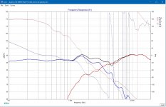
My spike issue was more apparent in the 2nd orderish crossover I worked up.
As soon as I started messing around with the 3rd order design it seemed much better and way better with reversing the tweeter polarity. Is that a good path to take or do I have to be concerned with delay and or phase issues that I am not aware of?
I do get that in the final design I need to add some resistor to the Tweeter to get it more matched to the woofer. I don't quite understand what you mean by lower the woofer some though. Is that more to flatten the impedance or for other reasons?
It may be that this is a breakup artefact, and unique to this axis. I'd just be bringing down this whole region as you are. Still there is the question of how much, but in general terms, not so much because of the peak.
Regarding the woofer sensitivity target I think I'd be seeing more of an opportunity a dB or two down, depending on what you put below it. I'd also bring the tweeter down.
Allen can you expand a little on Woofer sensitivity? Im about to upload a whole better crossover. Man this is so addictive to play with my hands are going numb. But I was able to get a notch filter in and a tweeter series resistor and now it is all much flatter. Im slowly finding my way around PCD and feeling a little more confident using it.
In that case you can save an Xsim project and post it here, when you want us to demonstrate or work on things.
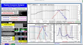
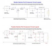
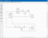
I just reverse engineered these dayton 2.5k crossovers that I am currently using. Horrible for these drivers would be a good starting point. And once again everything I look at now that I even know how to look comes back to tweeter polarity reversal solving a lot of issues near the woofers cone breakup area. I had one of these crossovers for free because one of the terminals fell off. These have a cardbord like backing that is heavily glued on making them hard to modify. I had already removed that to fix the terminal issue and am using it in the new center channel speaker. I called PE and asked for specs on this crossover. When I plugged those parameters in both PCD and XSim the results were so bad that I decided to RE the board. I indeed found different parameters than what I was told on the inductors. Wow it is SO BAD. If these speakers all sound this good with these crossovers I can only imagine what is possible. The 2.5k Dayton has a 4 & 8 ohm plug in jumper connection choice for using different woofer setups. I had an extra 4.0uf cap just sitting there and so I tried that in the software(s). After confirming that 8.0uf for the woofer in my drivers was indeed a slight improvement and once again seeing that a lot of problems would be solved with simply reversing the tweeter polarity I decided to move forward with what I have on hand. So on the center channel only I added in the unused 4.0 cap with a simple jumper. I reversed the polarity of the tweeters on FL FR & Cntr.
In an earlier post I stated that something was missing but I could not put my finger on it. Well I can now put it on at least this and I will add pics files etc shrotly.
The midrange as I had things before this change was from what I saw in PCD a graph that looked like it got hit by a tornado. Im really surprised by how much this simple change improved things. What was missing or at least one thing was a more clear midrange that resolved spatial movement and also the midrange in general. I can discern the scratchiness of the snare drum and its airyness now. the upper parts of the bass where effects are used and specifically where movement with the listening space jump out now as much to me as the difference of 1st listening to these Morel tweeters and realizing I had no idea what was REALLY THERE. Until I build some crossovers and can take care of the tweeter SPL with a series resistor I have just EQd thos areas down about 1 to 1.5 db.
no mod images
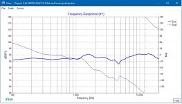
Where I was and what I have been listening to that I thought was good...LOL
Where I was and what I have been listening to that I thought was good...LOL
Attachments
-
 Dayton 2.5K XOVR MDT29 DSA175-8 no mods.jpg142.7 KB · Views: 60
 -
 Dayton 2.5K XOVR MDT29 DSA175-8 circuit no mods.jpg151.5 KB · Views: 74
 -
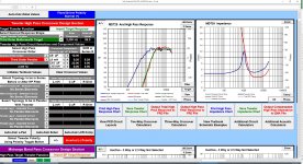
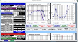
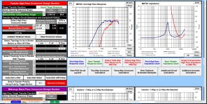 PCD8 T50 Dytn2.5k MDT29 DSA175-8 no mods pg3.jpg654.3 KB · Views: 72
 -
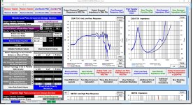 PCD8 T50 Dytn2.5k MDT29 DSA175-8 no mods pg2.jpg717.5 KB · Views: 71
 -
 PCD8 T50 Dytn2.5k MDT29 DSA175-8 no mods pg1.jpg773.3 KB · Views: 73
Allen I am not currently measuring. Im going off of just the response curves in the software. I have measured the whole enclosure though with DATs previously. I know there are ways to measure more with DATS like disconnecting one or the other driver. well at least i think thats right. Is that my next step? I need to do a new REW sweep and some REW measurements per speaker. My measure system has a snag though. My laptop that contains firewire for the Presonus has no HDMI for individual channel measurements. So I have been just looking at RTA on the laptop and using another HDMI PC to send pink white or other signals to each channel. This is slightly FUBAR because the loopback to eliminate noise is not incorporated.
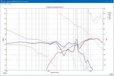
T50 Project Dayton Xovr no mods
Oh snap I just realized what you really meant. I just found out how to do that in XSim a little while ago and turned it on and made the colors match PCD. Im going to update some of the pics above to keep from posting too much pics or not as I can't edit it now. 😛
Oh snap I just realized what you really meant. I just found out how to do that in XSim a little while ago and turned it on and made the colors match PCD. Im going to update some of the pics above to keep from posting too much pics or not as I can't edit it now. 😛
Attachments
Last edited:
- Home
- Loudspeakers
- Multi-Way
- Project Polk T50