So, if the 3M is not in stock then the Wurth is an alternative, 710-61200823021, and Mouser has lots.
That blue LED number is a alternative.
That blue LED number is a alternative.
The rotary encoder for the input encoder board is also non-stocked, but he switched version is: 652-PEC11R-4020F-S12 may have to clip two leads, but it will work.
Also need a ribbon cable and the 8-pin ribbon cable connector ends for the input boards. I'll try looking for an alternate 8-pin .100X.100 connector for .050 ribbon.
The Encoder board for the input selection has the two pin holes for the switched version of the encoder, just in case the non-switched version wasn't available.
The part number above, 710-61200823021, is the 8 pin ribbon connector end. 🙂
The part number above, 710-61200823021, is the 8 pin ribbon connector end. 🙂
I would like for the input board to allow for one input on either end to go to a phone preamp instead of the line preamp. Were the gerbers made in KiCAD? I will try my hand with this modification if it is OK with john henry harris. I will be out for a week starting this Friday, so it isn't going to happen real fast. Just thinking out loud maybe jumper pads with solder pads on either side to allow someone to select which set of inputs are phono.
Not following the phone preamp verses line preamp but gerbers are gerbers these were produced using DipTrace software. The board is small enough that you could use the free version of the software and I can post the PCB layout file for you to play with.
OK, now that you mention it. I can just send the input directly to the phone preamp, then send it to the board. No changes would be needed. I was thinking switching before the phone preamp, but not necessary.
Making progress, have both the Arduino Mega and Nano uploaded, both analog boards populated, the volume encoder populated except for the 6 blue LED's and ribbon cable ends, the Display board populated except for the ribbon cable ends. Waiting on the input encoder board and power supply board to show up and the parts for both.

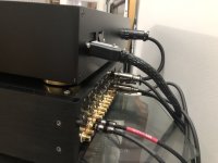
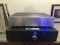
I use my preamp in both single ended, Turntable to phono-pre to line pre, and balanced from CD to preamp. And for grins here are more pictures of the preamp. It uses the previous generation of preamp controller, Arduino Nano based (no balance, standby, or display dimming) same good sound. The chassis is one I did CAD drawings for and had made at my favorite machine shop. The power supply chassis on top is from ebay and customized to the task.
And a rear view with connections and DC umbilical. Notice on the rear panel above the used RCA connections is a piece of 12 gauge copper wire, ground wire from Romex, bent in a small U and inserted from pin 1 to 3 on the Balanced input connector. My Preamp gain section is fully balanced so if you use single ended must ground the negative input.
And a rear view with connections and DC umbilical. Notice on the rear panel above the used RCA connections is a piece of 12 gauge copper wire, ground wire from Romex, bent in a small U and inserted from pin 1 to 3 on the Balanced input connector. My Preamp gain section is fully balanced so if you use single ended must ground the negative input.
Attachments
Last edited:
@johnhenryharris any tips on starting the newer microprocessor driven boards? I have checked the power supply and it is perfect.
As soon as you supply power to the boards the Arduino should power up, run through its setup and light up the display with a Zero and red on the center LED for mute, provided it has been loaded with the code. If it is not coming up, if you power the Arduino through a USB with the main power off does the board power light come on, if not you have a short in one of the boards. Unplug the Arduino and power it up, if that works connector it to the main board with all ribbon cables disconnected. Does the Arduino still power up, if not, the short is in the main board, if it does, power off and connect the encoder ribbon cable, power on, does it still work, if so power down and connect the encoder board to the ribbon cable and power up. If it doesn't power up the problem is in the ribbon or encoder. If it does power up then repeat with the display ribbon then board, powering off each time between, then the second relay board.. You can see you are trying to isolate the problem area.
So far I have seen: solder shorts on the display, a reversed polarity power connection (took out the Arduino and IR receiver), and a bad ribbon cable from main board to display. Also found one Arduino the was bad, would overheat in a couple minutes and freeze. Good luck and let us know what you find.
So far I have seen: solder shorts on the display, a reversed polarity power connection (took out the Arduino and IR receiver), and a bad ribbon cable from main board to display. Also found one Arduino the was bad, would overheat in a couple minutes and freeze. Good luck and let us know what you find.
I wasn't clear. I am powering up for the first time. I have powered up the selector board and encoder and it is working perfect. I do notice the selector encoder only moves the selections when turned clockwise. It does nothing when turned counter-clockwise.
I will power-up the other boards and see if it comes up as expected.
I will power-up the other boards and see if it comes up as expected.
Powered it up and everything worked great except for one left balance LED. I will troubleshoot that. May also order the LED's you recommended, these are not changing brightness very much. Scared the hell out of me, I powered it with a bench supply so I could limit current to 500mA. Well at volume step 255 it pulls about 500mA and tripped, LOL. I heard Wayne Coburn is releasing another preamp design, I may put this in that if it looks interesting, if not I'll retrofit it into my BA2018.
Are you getting the four steps of brightness on the balance LED's from pulsewidth modulation? I may try a 250 ohm resistor instead of the 180 ohm to get the LED down into a range where it will change brightness more.
The display dimming has four steps and uses PWM. The is a document on operations back a few posts, see post 535.
Also the input selector should go up and down turn right and left. If it continues to not work first check you are getting pulses to the Arduino per the schematic. Worst comes to worse you can mail one setup to me and I will troubleshoot it for you.
Also the input selector should go up and down turn right and left. If it continues to not work first check you are getting pulses to the Arduino per the schematic. Worst comes to worse you can mail one setup to me and I will troubleshoot it for you.
Last edited:

- Home
- Source & Line
- Analog Line Level
- Preamp Control - Volume, input, mute, remote