Calvin, it seems I don´t have most of the models you used...
But nevertheless thank you for posting.
But nevertheless thank you for posting.
Thanks dadod. Removed the supertex.txt include and it works 🙂
You’re welcome.
Hi,
For the models:
LSK389 and others may be found at the manufacturer Linear Systems website.
The Suffix co means it is model of Bob Cordell.
FZT are Fairchilds and the 2SK/2SJ are the as Dadod's.
Jauu
Calvin
For the models:
LSK389 and others may be found at the manufacturer Linear Systems website.
The Suffix co means it is model of Bob Cordell.
FZT are Fairchilds and the 2SK/2SJ are the as Dadod's.
Jauu
Calvin
I build the Calvin Power Buffer from post 39.
I am using different semis so i got a bit different conditions.
The input Fets are 2SK369 ( Idss higher then 12mA ) cascoded with J310. I get 2.4V Uds that way. With the 2SK369 that is not a problem because they have a high early voltage ( the Fet equivalent of it ). Instaed of FZT751 i use FZT753 because i have them. They can stand 2A instead of the 3A of the FZT751 so they are a little weaker. I get 0.175V through the 2.2 Ohm resistors so idle is a bit higher at ca. 80mA. I use 12V lead batteries. The FZT753 get hot but not extrem. I use the 10kOhm - 1nF output filter.
The circuit worked right away but there is some oszillation. Maybe i need an input filter too or the Fet choices are not that favourable. Anybody an idea ?
When i have made it work i will listen to it and also post some pictures.
I have both channels stable. I took out the 1nF, 10kOhm filter at the output and added a low pass of 1kOhm and 200pF at the input. Frequency response is now restricted to 700kHz -3dB. I will measure later and listen tomorrow.
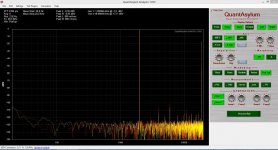
The buffer is very low distortion. Here is an overlay of the QuantAsylum 400 in loop back (red ) and the buffer ( yellow ). Distortion is under the resolution of the QuantAsylum ( -105 dB/V ). There is even some distortion cancelation going on because the amplitude of the buffer distortion is lower. Maybe that is the low output impedance driving the A/D converter.
Attachments
Calvin,
A bit late to join the discussion.
Firstly for line level I find the cascoded source follower already hard to beat.
If I would wish to have more current capability, I would put more in parallel, and modulate the lower FET with signal (CCS).
See :
http://www.diyaudio.com/forums/pass...urce-follower-configurations.html#post1592492
I have used Sziklai elsewhere. They can have too much gain and get unstable.
And then you end up using compensations. This ruins the simplicity of the circuit.
So in the end I rather use my DAO follower for really high current applications.
Or just use the BUF634 for instrumentation applications.
But I do like the JLH buffer for its elegance.
And you can use 2SK246/2SJ103 instead, which can still be had for reasonable price.
Patrick
I had to compensate and bandwidth limit this one too. 700kHz -3dB is decent though.
Lets see how it sounds. I build a lot of JLH buffers and they can be bettered.
Lets see how it sounds. I build a lot of JLH buffers and they can be bettered.
I've been working with buffers w/ gain and followers of the general form shown in the attached picture for a few years. In the case of the buffer w/gain, the input element (Q1) has been either a jfet or a mosfet w/feedback. The other gain element can be either a darlington or a mosfet. I1 has at times been a bipolar current source of some sort or a depletion mode mosfet source. Generally a compensation capacitor is needed across resistor R4. Vi has been an N-channel mosfet with gate connected to drain or an LED, depending on the voltage drop necessary for the proper voltage across I1.
The unity gain buffer actually came first, and has assumed several forms over the years. I have used both mosfets and jfets for input device Q3. The same variations used in the buffer with gain have been used for I2 and V3. Q4 has been a p-channel mosfet or a darlington.
The circuits simulate well, and sound good.
Attachments
Hi,
😉 hum, love when things work straight away ;-)
Joachim, the Rsx, RLx and CLx are no Filter but a simmed load of cable+Load impedance. The Rix, Cix are a input LP-filter. Response to a squarewave shows indeed a slight overshoot at the falling flanks but maybe tamed with a simple RL parallel network (27R||1µH/0R3) in series with the output.
I have no model of the SK369 so I simmed also for the BF862/SST4391, since it is closer to the SK369 in Transconductance and Id. Similar to Joachims transistor configuration the Idle current through the JFETs rise slightly to 6.5mA (Vds 4.31V) and considerably through the PNP to 75mA. Current through the 2R2 resistors rises to 81mA. FZT751 or FZT753 make hardly any difference.
Using the original BF862 Model of NXP the overshoot is completely gone. Maybe due to a lower Gate capacitance than the 2SK389/LSK389?
Btw: The small offset, is it due to matched SK369 or did You use the trimpot as in the schematic?
EUVL, yes, the simple cascoded JFETs are absolutely sufficient for higher impedance loads. The idea of the Sziklay is just to increase current drive capability/lower load impedance drive capability without giving up too much on simplicity and to stay with SE circuitry. The choice of parts is such that only active and SMD-parts are used instead of obsolete and throughholes.
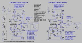
You can increase current drive further by going push-pull as for example in Your suggested circuits. This requires modulating the ´negative´ part of the circuits. You can do this with the shown Hybrid Cascode Compound Buffer (HCC) also by adding a simple RC series network. A technique Erno Borbely showed in his article about JFETs "JFETs: The new frontiers, part 2", Fig. 16A. This transforms the circuit from singleended to push-pull, but may be a bit harder to stabilize. see attached file, C103,R113, circuit B:.
jauu
Calvin
😉 hum, love when things work straight away ;-)
Joachim, the Rsx, RLx and CLx are no Filter but a simmed load of cable+Load impedance. The Rix, Cix are a input LP-filter. Response to a squarewave shows indeed a slight overshoot at the falling flanks but maybe tamed with a simple RL parallel network (27R||1µH/0R3) in series with the output.
I have no model of the SK369 so I simmed also for the BF862/SST4391, since it is closer to the SK369 in Transconductance and Id. Similar to Joachims transistor configuration the Idle current through the JFETs rise slightly to 6.5mA (Vds 4.31V) and considerably through the PNP to 75mA. Current through the 2R2 resistors rises to 81mA. FZT751 or FZT753 make hardly any difference.
Using the original BF862 Model of NXP the overshoot is completely gone. Maybe due to a lower Gate capacitance than the 2SK389/LSK389?
Btw: The small offset, is it due to matched SK369 or did You use the trimpot as in the schematic?
EUVL, yes, the simple cascoded JFETs are absolutely sufficient for higher impedance loads. The idea of the Sziklay is just to increase current drive capability/lower load impedance drive capability without giving up too much on simplicity and to stay with SE circuitry. The choice of parts is such that only active and SMD-parts are used instead of obsolete and throughholes.
You can increase current drive further by going push-pull as for example in Your suggested circuits. This requires modulating the ´negative´ part of the circuits. You can do this with the shown Hybrid Cascode Compound Buffer (HCC) also by adding a simple RC series network. A technique Erno Borbely showed in his article about JFETs "JFETs: The new frontiers, part 2", Fig. 16A. This transforms the circuit from singleended to push-pull, but may be a bit harder to stabilize. see attached file, C103,R113, circuit B:.
jauu
Calvin
Attachments
I selected the Fets and use the 180 Ohm, 220 Ohm combo. That brought the offset down to less then 2mV without trimming. The idle through the output transistors can of cause be lowered by lowering R3, R7.
Thanks for the output zobel. Using that i may be able to use less limiting at the input.
I will listen to the circuit as is and later try the modulated version.
With my bandwidth liiting the circuit drives the 10kOhm, 1nF load without any problem.
I could not see a difference on the scope with or without it so i took it out.
I have the buffer playing in my system. I have put potentiometers in front so i can substitute my standart line stage. My amps are quite sensitive so i can play loud.
More to come. When the listening session is over i will also try the driven CCS.
More to come. When the listening session is over i will also try the driven CCS.
When transparency is your idea of high fidelity this is the deal.
The buffer sounds very open and revealing. It has enormous speed and slam. Focus is very good and 3-D effect tight. Gone is the slight romance of my JG2 line stage.
Tonal balance is neutral, tonal colours come out well if the material is good enough.
This is certainly a high feedback sound but it is not harsh or spitty. So far i am impressed.
I will try the driven CCS now.
I agree. Amazing for me is in this case the fact, that there are no comercial line amps with this topology available on the marked. Most models use still the unwanted voltage gain factor between 5 and 20 instead unity gain despite the most presently commercial power amplifier also use a voltage gain factor between 30 and 60.When transparency is your idea of high fidelity this is the deal.
The buffer sounds very open and revealing. It has enormous speed and slam. Focus is very good and 3-D effect tight. Gone is the slight romance of my JG2 line stage.
Tonal balance is neutral, tonal colours come out well if the material is good enough.
This is certainly a high feedback sound but it is not harsh or spitty. So far i am impressed.
I will try the driven CCS now.
I use a preamp with the topology according Andrea Ciuffoli's power follower - go to
http://www.audiodesignguide.com/my/Follower_99c.gif
but with only 300 mA idle current (14VDC supply voltage - this means arround 8W power loss for both channels).
This preamp blown away all me known top class commercial preamps independently from the rest of the used audio components.
The disadvantage from the parasitic input- and reverse capacitance of the MOSFET isn't audible.
only disadvantage remains: All unity gain power amps cannot deliver full power together with such preamps. But such power amps are very rare as I know.
Last edited:
Hi,
I marked that day at as a very special day in my diary 😀
😀
Will You also test the all-FET Version with e.g. Zetex ZVP2106 or similar?
jauu
Calvin
It´s only a first proto and already impressing Joachim.So far i am impressed.
I marked that day at as a very special day in my diary
😀Will You also test the all-FET Version with e.g. Zetex ZVP2106 or similar?
jauu
Calvin
I will try the driven CCS today. Sure, if you wish i can try the all mosfet version.
First i will build the driven CCS without other changes to direct compare to what i have.
I will then add the zobel and make less bandwidth limiting at the input if that is posible.
First i will build the driven CCS without other changes to direct compare to what i have.
I will then add the zobel and make less bandwidth limiting at the input if that is posible.
- Home
- Source & Line
- Analog Line Level
- Preamp-Buffers - simple idea