I just build it, i am a practical person.
I just can not stand the threads where the experts are talking everything to death and nothing sees the light of day. I identify excellence when it happens though.


Hi,
just OT:
please stop quoting complete posts.
You may cite the post number for reference or cite a short important excerpt.
You may of course post schematics, details or whatever You like in the Masterpiece thread, but I preferred when the main discussion about these buffers keeps on going here.
- The Masterpiece thread´s main theme is about RIAA amplification and not about Preamp Buffers in first place. The kind of buffer is of rather low importance.
- It has reached a length that would make it hard to find or follow an issue of low importance.
- Conceptually the RIAA part and Buffer part differ. A rather complex complementary design on one hand and a simpler single-gender design -SE from evolution- on the other.
jauu
Calvin
Calvin, is it alright when we use your buffer in the output stage of the Masterpiece ?
I will try to restrict my technical experience with your buffer to this thread here.
What i will do now is load it with 100 Ohm and measure distortion again.
I will try to restrict my technical experience with your buffer to this thread here.
What i will do now is load it with 100 Ohm and measure distortion again.
but post52 does not have the "expansion" arrows grid...................Andrew, if I click on the Thumbs they open to nearly full screen size on my monitor and are easy to read.
With the result it is too small (for me) to accurately compare to the earlier posts8, 22 & 39.
I can easily read all three of the earlier posts.
Last edited:
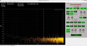
Here is the distortion measurement with 100 Ohm loading. Again under my maesurement threshold. Yellow is the buffer and red the loop back.
This could also be a great head phone driver.
I will now try to push it out of class A. Asuming that the buffer can push 100mA i have to use a resistor with less than 40 Ohm. I will use a really taxing 15 Ohm.
This could also be a great head phone driver.
I will now try to push it out of class A. Asuming that the buffer can push 100mA i have to use a resistor with less than 40 Ohm. I will use a really taxing 15 Ohm.
Attachments
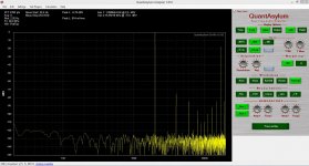
OK; now we are talking. The plot reveals the real nature of the beast.
Distortion is still low with second the highest at -75dB. There is a really nice progression of the higher harmoincs being lower and lower the higher the order. Intermodulation shows classical " children "
We are talking now 4V P-P into 15 Ohm that is nearly 0.3W.
Distortion is still low with second the highest at -75dB. There is a really nice progression of the higher harmoincs being lower and lower the higher the order. Intermodulation shows classical " children "
We are talking now 4V P-P into 15 Ohm that is nearly 0.3W.
Attachments
Hi,
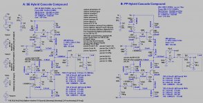
Andrew, here´s #52 again.
I only changed the 180R R102 into two resistors R102a (105R) and R102b (75R) to achieve symmetrical current swing in the upper and lower half of the circuit.
Joachim, of course may You use the Buffer. I just liked to keep the discussion about it here in its original thread. 😉
The modulated Buffer simmed also well into loads as low as 16R and 2Vrms with increased idle current and reduced emitter- and output resistors. The output transistors might need to be doubled to handle power dissipation though.
jauu
Calvin
Attachments
Hi,
made a first single sided all-SMD layout. Without power supply caps and without cooling-fin areas for the output transistors a single channel of the circuit could fit within ~22x33mm.
 Thinkin bout how to name it .... maybe MightyMouse?
jauu
Calvin
made a first single sided all-SMD layout. Without power supply caps and without cooling-fin areas for the output transistors a single channel of the circuit could fit within ~22x33mm.
Thinkin bout how to name it .... maybe MightyMouse? jauu
Calvin
I would call it The Rat Pack 🙂
I have installed a second set of output jacks and the zobels. That way i can compare both options.
I have installed a second set of output jacks and the zobels. That way i can compare both options.
Hi,
maybe of interest. While the output transistors eventually are cut off when the circuit is driven into class-AB the JFETs are not.
This results in a steady current of >0 through the upper and lower half (R103 and R108), similar to a non-switching class-AB circuit.
jauu
Calvin
maybe of interest. While the output transistors eventually are cut off when the circuit is driven into class-AB the JFETs are not.
This results in a steady current of >0 through the upper and lower half (R103 and R108), similar to a non-switching class-AB circuit.
jauu
Calvin
This is a very clever circuit. Thanks for that additional information.
I have installed the zobels and i have cut the input filter in halve so response is now up to 1.5MHz -3dB. The 10kHz 20V square is now a more or less exact copy of my generator that has a small over and undershot anyway. I will put it back in the system.
I am having fun, big time.
I have installed the zobels and i have cut the input filter in halve so response is now up to 1.5MHz -3dB. The 10kHz 20V square is now a more or less exact copy of my generator that has a small over and undershot anyway. I will put it back in the system.
I am having fun, big time.
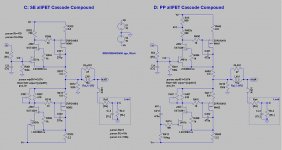
Calvin, could you please post a schematic of the mosfet version ? That would safe me a lot of time. I have seen the schematic but it was not dimensioned and did not have the driven CCS.
Thanks, i only have ZVP3306A with a theshold voltage of 2,6V. I think when i put 2 in parallel with separate source resistors it should work.
Hi,
the ZVP3306A has a similar Vtreshold as the ZVP2106G after Fairchild DS.
It has lower capacitance and probabely higher Transconductance at the chosen current. So the overall values of the cascode Drain resistors (750R) should work fine. At least in the Sim there´s no significant change in Isource of the MOSFETs. But due to the different transconductance the combination of 500R + 250R will give too much modulation of the negative side. You may try with 120R + 630R instead (the 120R towards Vp!).
The output inductance may be smaller, around 2.2µH.
jauu
Calvin
One ZVP3306A has around half the transconductane of the ZVP2106G and half the current capabilty so i though two in parallel should do the trick.
What do you think and how should i set up the resistors ?
What do you think and how should i set up the resistors ?
Hi,
Joachim, are those figures measured at the bias current?
Unfortunately is the resolution in Fairchilds DS too low for the desired bias point.
But the higher transconductance of the 2106 comes to effect at higher drain currents. Around 50mA both the 2106 and the 3306 seem close, the 3306 maybe even higher.
In our case the only proof of the pudding would be to measure the signal current swings through the source resistors R406/411 or the 2.2R resistors R403/408 and to trim till symmetry is achieved.
Increasing R13/decreasing R402b accordingly increases the modulation and the current swing of the negative part. The opposite will increase the upper parts current swing.
A hint may also to trim V(out) to THD-minimum at the treshold of class-A to class-AB. The closer to symmetry the currents are, the higher the treshold to class-AB will be.
jauu
Calvin
- Home
- Source & Line
- Analog Line Level
- Preamp-Buffers - simple idea