I´m not aware of any John Curl schematic where this buffer was used.
(It´s from a chinese ebay seller if I´m not mistaken.)
What John did use, is a similar configuration without cascode for the
output of the JC-2 (ML-1) phono stage. It´s within the feedback loop
in this phono stage, though.
Correct, why would one want to cascode those Jfets when they are low capacitance anyway, for use with 170/74 pair it makes more sense.
That schematic is actually from pioneer, in the late 1970s this was their favourite buffer ableit with 170/74, used in all their medium to high end models.
Hi,
circuit A, the simple source follower sounds very natural, but is what I´d call a connoiseur´s circuit. It is excellent for classical music, but may lack a little bit on authority or massive slam with Pop or Rock. This is a sonic impression not just of me but also of different persons. The ´weight´ or impact seems to be directly related to the amount and quality of decoupling capacitance in the power supplies. More seems better here.
circuit B already adds the weight and authority with less demand on supply capacitance.
Since George´s driven cascode shows more similarities to circuit B in circuit structure and in simulation, it´d be interesting to hear, if there are any differences and how they manifest.
Both circuits are suited only for higher load impedances from 1-2kOhm up.
The driven cascode allowing for higher maximum output voltage at the cost of slightly more loss in tranfer function and higher parts number count.
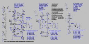
As one can see from the wiper position and the currents through each Poti-part the NJFET and PJFET differ considerably. The part of the poti towards the negative branch is set to mere 24Ohms. Hence roughly half the current is running through the lower part and wiper of the poti. I wouldn´t want to allow for more than 1/4 to 1/5 of the branches current, or max 1mA, running through the trimpot due to quality of wiper contact and high temperature coefficient.
The combination of 2SK170/2SJ74 sims clearly better with regard to THD.
Also, using EUVLs trick of matching N- and P-JFETs transconductance curves by adding a small (or slightly higher) source resistor to a 2SJ74 with slightly higher IDss might even render the trimpot obsolete. At least it´d reduce the amount of current running through the trimpot.
Still though, does the driven cascode not match the cascoded compound circuits in THD and drive capablity. This would require different parts allowing for idle currents around 25mA.
jauu
Calvin
circuit A, the simple source follower sounds very natural, but is what I´d call a connoiseur´s circuit. It is excellent for classical music, but may lack a little bit on authority or massive slam with Pop or Rock. This is a sonic impression not just of me but also of different persons. The ´weight´ or impact seems to be directly related to the amount and quality of decoupling capacitance in the power supplies. More seems better here.
circuit B already adds the weight and authority with less demand on supply capacitance.
Since George´s driven cascode shows more similarities to circuit B in circuit structure and in simulation, it´d be interesting to hear, if there are any differences and how they manifest.
Both circuits are suited only for higher load impedances from 1-2kOhm up.
The driven cascode allowing for higher maximum output voltage at the cost of slightly more loss in tranfer function and higher parts number count.
As one can see from the wiper position and the currents through each Poti-part the NJFET and PJFET differ considerably. The part of the poti towards the negative branch is set to mere 24Ohms. Hence roughly half the current is running through the lower part and wiper of the poti. I wouldn´t want to allow for more than 1/4 to 1/5 of the branches current, or max 1mA, running through the trimpot due to quality of wiper contact and high temperature coefficient.
The combination of 2SK170/2SJ74 sims clearly better with regard to THD.
Also, using EUVLs trick of matching N- and P-JFETs transconductance curves by adding a small (or slightly higher) source resistor to a 2SJ74 with slightly higher IDss might even render the trimpot obsolete. At least it´d reduce the amount of current running through the trimpot.
Still though, does the driven cascode not match the cascoded compound circuits in THD and drive capablity. This would require different parts allowing for idle currents around 25mA.
jauu
Calvin
Attachments
Arent the Jfets in the original post 10 already bootstrapped, the only diffrence is that you are removing the 22 ohm resistors.
I moved R2, R7 from the output to the sources of the JFETs, and no JFETs were not bootstraped before and are not now.
Hi,
one could add a pair of large caps in parallel to R2 and R7 to bootstrap.
Just with the resistors it doesn´t make much difference if R2/R7 are connected to the JFETs sources or to the output. The Vds of the JFETs vary by ~1/2 the output voltage swing. The caps would make Vds constant, like in a true cascode.
jauu
Calvin
Hi,
one could add a pair of large caps in parallel to R2 and R7 to bootstrap.
Just with the resistors it doesn´t make much difference if R2/R7 are connected to the JFETs sources or to the output. The Vds of the JFETs vary by ~1/2 the output voltage swing. The caps would make Vds constant, like in a true cascode.
jauu
Calvin
My exact thought.
I´m not aware of any John Curl schematic where this buffer was used.
(It´s from a chinese ebay seller if I´m not mistaken.)
What John did use, is a similar configuration without cascode for the
output of the JC-2 (ML-1) phono stage. It´s within the feedback loop
in this phono stage, though.
Yes it was a sold on ebay and John Curl only said it look good, I never said he used it or designed it.
Cheers George
You can improve this to bootstrap cascode.
I think for memory Thorsten Loscetch suggested that also over at the other place years ago.
If I did that would the offset trimmer still fucntion.
Also by doing what you and Throsten suggest what advantages will this make? eg is output impedance lower or higher? thd better? current output better?
Cheers George
Hi,
one could add a pair of large caps in parallel to R2 and R7 to bootstrap.
Just with the resistors it doesn´t make much difference if R2/R7 are connected to the JFETs sources or to the output. The Vds of the JFETs vary by ~1/2 the output voltage swing. The caps would make Vds constant, like in a true cascode.
jauu
Calvin
Hi Calvin, what size caps are you talking about, electro or plastic? I've some Sanyo 22uf 25v oscons? And do I leave the R2 & R7 as is, connected to the output?
In laymans terms what will this achieve and does the offset adjust still work the same?
Cheers George
Last edited:
Hi,
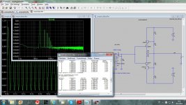
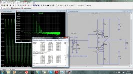
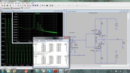
Dadod, You´re sure that te parameters for THD-simulation in Your .asc are complete and correct?
Is there a plotwinsize=0 command and are sim-time and related parameters as required for a reasonable THD-sim?
I get certainly worse results, around 0.001% for 1Vrms@1kHz.
jauu
Calvin
Dadod, You´re sure that te parameters for THD-simulation in Your .asc are complete and correct?
Is there a plotwinsize=0 command and are sim-time and related parameters as required for a reasonable THD-sim?
I get certainly worse results, around 0.001% for 1Vrms@1kHz.
jauu
Calvin
I put on the 22uf 25v Sayo Oscons, had a listen and yes I believe it sounds a maybe bit better/cleaner but not by much. .00036% THD is fine by me as well.
BTW are the Sanyo Oscons a good cap in this postion?
Cheers George
BTW are the Sanyo Oscons a good cap in this postion?
Cheers George
Last edited:
Hi,
Dadod, You´re sure that te parameters for THD-simulation in Your .asc are complete and correct?
Is there a plotwinsize=0 command and are sim-time and related parameters as required for a reasonable THD-sim?
I get certainly worse results, around 0.001% for 1Vrms@1kHz.
jauu
Calvin
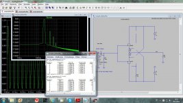
Those are the parameters I am using.
.options plotwinsize=0
.options method=gear
.options numdgt=7
.param Freq=20
.param numcyc=20
.param dlycyc=5
.param FFT=2**16
.param simtime=numcyc/Freq+dlytime
.param dlytime=dlycyc/Freq
.param timestep=(simtime-dlytime)/FFT
.four {Freq} V(Vin) V(Vout)
.four {Freq} 4 V(Vin) V(Vout)
;
.tran 0 {simtime} {dlytime} {timestep}
.option numdgt=15
.option reltol=1e-6
.option ptrantau=0
;
;ac dec 1k 1 1G
Yes it was a sold on ebay and John Curl only said it look good, I never said he used it or designed it.
Cheers George
John seems to like the type "A" circuit:
http://www.diyaudio.com/forums/anal...rch-preamplifier-part-ii-750.html#post3431096
Hi,
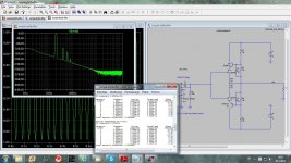
Dadod, then we are using different models.
These are mine:
.model 2SK246 NJF(Beta=1.07m Rs=56.76 Rd=56.76 Betatce=-.5 Lambda=2.8m Vto=-2.638 Vtotc=-2.5m Cgd=10.38p M=.4373 Pb=.3905 Fc=.5 Cgs=6.043p Isr=112.8p Nr=2 Is=11.28p N=1 Xti=3 Alpha=10u Vk=100 Kf=1E-18 Af=1 mfg=Toshiba)
and
.model 2SJ103 PJF(Beta=2.197m Rs=76.76 Rd=76.76 Betatce=-.5 Lambda=735.3u Vto=-2.037 Vtotc=-2.5m Cgd=18.95p M=.5045 Pb=.3905 Fc=.5 Cgs=17.02p Isr=38.48f Nr=2 Is=3.848f N=1 Xti=3 Alpha=10u Vk=100 Kf=1E-18 Af=1 mfg=Toshiba)
What are Yours?
jauu
Calvin
Hi,
Dadod, then we are using different models.
These are mine:
.model 2SK246 NJF(Beta=1.07m Rs=56.76 Rd=56.76 Betatce=-.5 Lambda=2.8m Vto=-2.638 Vtotc=-2.5m Cgd=10.38p M=.4373 Pb=.3905 Fc=.5 Cgs=6.043p Isr=112.8p Nr=2 Is=11.28p N=1 Xti=3 Alpha=10u Vk=100 Kf=1E-18 Af=1 mfg=Toshiba)
and
.model 2SJ103 PJF(Beta=2.197m Rs=76.76 Rd=76.76 Betatce=-.5 Lambda=735.3u Vto=-2.037 Vtotc=-2.5m Cgd=18.95p M=.5045 Pb=.3905 Fc=.5 Cgs=17.02p Isr=38.48f Nr=2 Is=3.848f N=1 Xti=3 Alpha=10u Vk=100 Kf=1E-18 Af=1 mfg=Toshiba)
What are Yours?
jauu
Calvin
I use those from syn08 http://www.diyaudio.com/forums/software-tools/101810-spice-simulation-49.html#post1420730
I did not compare to see if differente.
dado
Hi,
this is mine.
It differs to Dadod´s only by .param numcyc and the addition of settable delaytime .param dlytme and associated .param Square=1 or 0.
Setting the parameters to Dadod´s values still resulted in a THD-difference.
The models seem to be identical. So I don´t have an idea where the differences may come from.
jauu
Calvin
Attachments
- Home
- Source & Line
- Analog Line Level
- Preamp-Buffers - simple idea