

Parts ordered.
Luckily, I was able to keep the cost below $85 to build a pair since I already had most of the big ticket items in my stash.
Probably going to replace the SMPS unit in my Holy Grail Follower amplifier with these. I just wasn’t completely satisfied with the background noise I was hearing when close to the speaker.
Another journey will begin soon… 🙂
You could try a two step approach. Assemble first supply without rectification part, and connect SMPS output to the C2 pads (without capacitor there). RF filter and regulator could filter enough of noise. Though, part of noise at amplifier’s output is coming from the SMPS radiated noise, which bypasses any supply or filtering. If not good enough, you can move to transformer + active rectifier.
Still luxuriating in the sound from just having the tweeter amps converted. (compression driver tweeters)
Hope to get the other two done by this weekend.
I could be dreaming; my record is chequered with broken dreams of audio nirvana that wasn't there
- but I think you are going to be very pleased, Vunce.
I have a feeling you will be happier with transformers. I love the practical aspects of SMPS but whether it really is there or not I always hear something riding the music in the high frequencies with SMPS. I hear this all of the time with digital gear but it is accentuated when SMPS are employed and seems to be ameliorated, but never quelled, with a linear supply. But, that is the best we can do ...
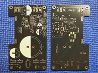
The PSU without a name, AKA: R25, journey has begun.
Most components are populated, but stopped at this point because I am still undecided what shape of aluminum Q9 will be undermounted to for heatsinking. I'd like to mount both boards on a single piece of thick aluminum plate to have a bipolar psu that can be used universally in different amplifiers. Drawback for this method is fitment won't be ideal depending on amp chassis. Probably best to build specifically for the amp it will be used in and forget the "universal" useage. Just build more R25's!!
I did find a small tweak for the BOM...
Currently the trimpot is a 'Y' version with offset pins, for best fitment an inline 'W' version should be used.
Here's the Mouser link for the trimpot:
https://mou.sr/429Agb1
Attachments


Tombo,
I was thinking number three would go easy.
It worked fine connected to the 100R load.
I messed it up by forgetting to connect the input load resistor which also affects bias on the TDV amplifier when connecting to the amplifier.
Familiarity breeds negligence in my case.
So I measured the voltages at the points specified:
2 - 33.3
3 - 0
4 - 32.3
5 - 0
6 - 43
All are negative since I have it connected for negative voltage - used the plus out for the ground.
Looks like the mosfet is OK. Both of the LEDs are working - the red one only lights when I turn it off after screwing up.
So now it acts like it did with my previous mistakes - no regulation - load gets plenty warm but no regulation but with green LED lit and the red doing as i stated above.
Any idea what I destroyed?
Your counsel and help is needed, yet, again.
Thanks and take care,
I see that you’ve used initial BOM from the project zip file. Both shared Mouser cart and new separate BOM have the correct 220 uF capacitor and 10K trimmer.Currently the trimpot is a 'Y' version with offset pins, for best fitment an inline 'W' version should be used.
Voltages are weird. Never mind what is used as a ground. Did you measure voltages between point 1 (as marked on the picture) and all other marked points, always keeping one probe at point 1?used the plus out for the ground.
Good catch Gary. A bit of precision bending and my 'Y' transformed into a 'W', hehe!!
Since this board only has a few SMD components, they are all soldered with an iron.
The caps and EMI filter were soldered with 1.2mm chisel tip(T15-D12) and a 1mm bevel tip(T15-BC1) for the opamp.
Kester 0.015" '44'rosin core solder, apply a small blob of solder to a corner opamp pad, spread flux on each pad with the tip of a toothpick, pick and place the opamp into position. Wet the bevel tip and touch the edge of the opamp pad while gently holding the opamp in place with tweezers. As the solder melts drag outwards. Then do the same for the corner leg diagonally across, now that the opamp is stable the 6 other legs can be finished off. Be careful not to overheat the little bugger!
Hi Tombo,
I used the Mouser cart linked in the first post and it has the Y version in it, strange?
I used the Mouser cart linked in the first post and it has the Y version in it, strange?
Mouser cart was updated, along with the Excel BOM, before your order. If I check Mouser cart, it is presenting the right trimmer (with inline pins) for me. Is it the same for you?
EDIT:
Hmm, now I wonder if picture at Mouser is simply wrong and part number is for trimmer with offset pins.
EDIT:
Hmm, now I wonder if picture at Mouser is simply wrong and part number is for trimmer with offset pins.
Yeah, that’s the strange part, I just checked and the linked cart and it shows the Y trimpot and the smaller footprint capacitor??
Damn, confirmed that Y is for offset pins and part picture is wrong. Another BOM update is due.
220 uf capacitor is correct 667-EEH-AZA1V221B, which has 5 mm pitch
220 uf capacitor is correct 667-EEH-AZA1V221B, which has 5 mm pitch
Yes, they sure were!
I was thinking of my ground instead of the actual ground.
Input 43.76
Output 43.75
2 - 10.4
3 - 6.69
4 - 11.34
5 - 43.76
6 - 0.45
Sorry about that.
I was thinking of my ground instead of the actual ground.
Input 43.76
Output 43.75
2 - 10.4
3 - 6.69
4 - 11.34
5 - 43.76
6 - 0.45
Sorry about that.
Tombo, if you’re going in for an update please double check on capacitor C6, I believe it’s still the smaller 3.5mm footprint.
EDIT:
C6 is indeed the 5mm LS cap👍🏻
EDIT:
C6 is indeed the 5mm LS cap👍🏻
Last edited:
nput 43.76
Output 43.75
2 - 10.4
3 - 6.69
4 - 11.34
5 - 43.76
6 - 0.45
Check MOSFET by measuring resistance between pins 2-3. If there is a short circuit, replace MOSFET. Check D10 for short circuit as well.
Time for my ‘beauty sleep’ is approaching so I won’t be able to assist till tomorrow. If stuck, you could also proceed with the fourth supply.
- Home
- Amplifiers
- Power Supplies
- Power Supply with Active Rectifier, RF Filter and Super-Regulator