Vunce,
Yes I have the 4 - 10mf Cap bank connected to C2 with wires I soldered to the pins of C2 - 12 gauge was handy so that is what I used. As close together as one can have them and still be able to connect them. Using O connectors and brass screws - my favorite connector. I learned to make everything modular so it is easy to take it apart.
Yes I have the 4 - 10mf Cap bank connected to C2 with wires I soldered to the pins of C2 - 12 gauge was handy so that is what I used. As close together as one can have them and still be able to connect them. Using O connectors and brass screws - my favorite connector. I learned to make everything modular so it is easy to take it apart.

Voltage drop over regulator can be measured between +pin at C2 and +output of the supply. Some 1-1.5V is a good start. In your case, critical minimum is 0.6V.I get the feeling the regulator wants more voltage drop than I expected - but I am not quite sure where to measure the before and after difference.
Luckily I have access to +pin of C2 - that could be tricky in some installs..
I did raise the voltage without any problems but I was not referencing between C2+ and + output.
No question the amplifier is quieter. One would think this could be gilding the lily with a power buffer but, so far, I think R25 and ra7's TDV-51 is a happy match.
As soon as I get the left channel tweeter amp (<400 Hz) I will be able to get a real idea of how R25 affects the sound.
From just one channel my comments are suspect but I heard no typical regulator running out of steam sound. When installed on the >400 Hz woofers we shall hear how it does. My intention is to run more current through the "bass" amplifiers.
I have presumed that adjusting the trimmer is a bad idea while the amplifier is on and connected to a speaker. Is that the correct presumption?
Thanks, again, Tombo
You can adjust output voltage as you like while everything is powered. There is absolutely no risk, if dissipation will not be too high.I have presumed that adjusting the trimmer is a bad idea while the amplifier is on and connected to a speaker. Is that the correct presumption?
If adjusted output voltage is higher than available at input, red LED will start to flash. But before that clear indication, there is some 0.3V gray area, because voltage at C2 is not clean stable DC but DC + some 0.7V AC at 120 Hz (ripple). So, at one point, input voltage will be lower at input than required, 120 times per second, each time for millisecond or so. You could hear that as some fuzz or different, depending on specific amplifier. Red LED will not flash at that condition, but only if input voltage is all the time below required. Probably, that’s the condition you described in previous post.
Go ahead, and turn trimmer clockwise to request higher output voltage. Red led must start to flash and output voltage will gently go down a little and than slowly up again, in rhythm with LED flashes. Sort of a hiccup mode.
Yes, I hear the hiccup when turning the amplifier off accompanied by the red LED flicker in unison.
My curiosity is whether there is a difference in sound quality with more or less voltage drop.
Have to work today - can't wait to get home and get another amplifier R25 equipped.
My curiosity is whether there is a difference in sound quality with more or less voltage drop.
Have to work today - can't wait to get home and get another amplifier R25 equipped.
Well, Tombo, I have a new problem with module #2.
Red and green LEDs light but the voltage cannot be adjusted; turning the trimmer does nothing much - 0.5 volt or so. Around 45 volts output. The resistors heat up.
I have checked the board repeatedly and there is nothing inserted incorrectly.
Any obvious thing to check? Getting ready to look at the opamp - but it looked fine. I will try re-soldering.
At your leisure. I doubt you are looking at this today.
Take care,
Luckily, there is an email notification on new posts.I doubt you are looking at this today.
With supply powered off, measure resistance between pins 2 & 3 of SUP70101. If there is a short circuit, replace MOSFET.
If MOSFET id OK, on powered supply, but with amplifier disconnected, measure voltages between the following points, as marked on the picture.
1-2, 1-3, 1-4, 1-5, 1-6. Add voltages at input (+pin of C2 to ground), and voltage at supply output.
EDIT: as you intended, after checking MOSFET, check soldering on opamp.
Last edited:
Must have been the opamp - all is well now. I had never soldered in an SMD opamp - must have got lucky with the first. I will be be more certain of the next two before applying power.
Hope others will benefit from my mistakes with your pictorial and written guidance.
Now I am curious - when you get the time - what voltages should be at those points?
THANKS again for your patience and help.
Listening to only one channel and that one channel has only one of the two amps converted - I know this is, at best, anecdotal, but the image width that the equipped channel gave was close to an unbelievable surprise. I can only assume this comes from the low noise of the supply. I listened to the other channel in mono for quite a few days while i figured out where best to place R25 so I think I can say with certainty that the sound was pleasant but more confined to the speaker. No comparison to the 1/2 R25 channel. I have found listening to my speakers in mono - one speaker at a time - is very instructive.
Cannot wait to hear what both tweeter channels sound like with this supply.
Take care,
When soldering with the standard soldering iron, more than once I had the same problem. On the first look, it looks well soldered but it was not. So, adding a little flux and repeating each pin will solve the problem.Must have been the opamp - all is well now
My favorite term from the Pass Labs forum section is FAB (Fearless Amplifier Builders). Burn some components, learn from the mistakes, success is right ahead.Hope others will benefit from my mistakes
Voltages are related to set output voltage, so they are not fixed but their ratio can eventually help me determine what is wrong with the circuit.Now I am curious - when you get the time - what voltages should be at those points?
Just hearing from 500 Hz up I can say R25 is a requirement for MOFO style amplifiers.
Time will tell, of course - I cannot imagine my impressions changing.
Nothing of importance is lost; the sound is demonstratively better. In fact, it is so much better I wonder if there was something wrong with the original supply which was the same power transformer - prasi's LT4320 board - ZM cap bank with 4 - 10mF caps - HAMMOND 100 mH - 5A choke - and another ZM cap bank with the same capacitors.
One is left with a much more compact amplifier with a soft start - before I used a CL-60 which I would bypass after 15 seconds - so now one switch is all that is needed.
Maybe there is an even better way to do what Tombo has designed R25 to do? I am not aware of it which never means much. I do know this is much better than what it replaced. I cannot imagine a more elegant solution.
I do not hesitate to say that those who are using MOFO style amplifiers have a very pleasant surprise waiting for you if you install R25 into your amplifiers.
Maybe the below 500 Hz amplifiers will not gain as much? I will find out soon. But then it could be even more important there.
Thanks, Tombo. R25 is a lovely work of audio art.
Yes, I know the voltages would be dependent on the input voltage - could be interesting as a basis if you told us what voltages you get with the power transformer you are using. One could scale from there. When you have nothing better to do ...
Nothing better to but developing fine hardware at own cost & time, measuring and publishing results, helping out the builders AND making a list of all possibilities. Preferably 24/7 and for free of course 🙂
Please guess what I forgot to delete from the last shopping list update:
Please guess what I forgot to delete from the last shopping list update:
Attachments
Last edited:
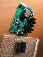
Heatsink😂
Lookin good JP.
Solid impressions Rick, looking forward to building mine. The Yellow van is delivering my JLCPCB order today😉.
Lookin good JP.
Solid impressions Rick, looking forward to building mine. The Yellow van is delivering my JLCPCB order today😉.
Thanks. Also the extra capacitors. It is not bright to name shopping list updates with just a incremental number when updating/adding items.
BTW the effect even of a less sophisticated regulated PSU versus just caps is impressive just like replacing switchers of sources and DACs for linear PSUs.
Now guess what your next favorite amplifier, source or DAC has for a PSU 🙂
BTW the effect even of a less sophisticated regulated PSU versus just caps is impressive just like replacing switchers of sources and DACs for linear PSUs.
Now guess what your next favorite amplifier, source or DAC has for a PSU 🙂
Last edited:
At least, you PS looks very nice with that heatsink. 😀Please guess what I forgot to delete from the last shopping list update:
There is not much surprise that you find sound better. MOFO style amplifiers have a very low PSRR or isolation factor between supply and amplifier output. In fact, only 20 – 30 dB or 10 – 30x. So, ripple and modulation of rails by AC load, can audibly leak to the amp output. My motto is that good PS is a foundation for a good amplifier. There is a lot of latter, but unfortunately not enough of the former.the sound is demonstratively better.
Nothing wrong with your former supply. This supply is simply technically better. Not by accident, those technical properties translate usually (but not guaranteed in every case) into the better sound.I wonder if there was something wrong with the original supply
I wish there was any very good solution available here at diyaudio, but unfortunately it was not. So I decided to make one (R21). To repeat myself from the R21 explanation - “Silly me. It was not an easy task.” 😆Maybe there is an even better way to do what Tombo has designed R25 to do? I am not aware of it which never means much.
Anyway, I’m happy that anyone besides me can achieve better sound by using my designs. 🙂
Definitely looks OK but I still think it is a gadget without benefits and costing too much. The aluminium clip damages the TO220 tab and the mechanical force is not that of M3 bolts. Still unsure about how galvanic isolation works as the clip touches the tab or did I mount it wrong? Edit: I see I did mount it wrong. Never again this one. Thankfully I haven't powered it on yet.At least, you PS looks very nice with that heatsink. 😀
That is a nice motivation!Anyway, I’m happy that anyone besides me can achieve better sound by using my designs. 🙂
Last edited:
Vunce,
I look forward to hearing what you hear with R25..
One wonders if Tombo could come up with an electronic choke for the choke. I know this would be called a gyrator. I have no idea if such a thing is possible for this application but if anyone could make a good one I have a good idea who it would be.
Tombo,
I think many assume (as I did) the buffer aspect of the MOFO makes its power supply less critical. I think after hearing what happens with R25 that is an erroneous assumption.
It makes sense to me that the power supply should be more complicated than an, ideally, simple circuit - maybe one can have one or the other but not both? In each case - a complicated circuit with a complicated (complicated meaning lots of active devices) power supply will probably not sound too good either.
There is much musical pleasure awaiting those who use this marvel.
I think problem is that you didn't apply clip as is meant. MOSFET seems very low positioned at your board.The aluminium clip damages the TO220 tab
Yeah like usual short connection and TO220 till the point where the pins get wider and can not go deeper. Also the force against the MOSFET body felt wrong and the MOSFET changed position because of the clip both in unsoldered state and when trying to mount the set before soldering.
I will order a new MOSFET.
I will order a new MOSFET.
Last edited:
- Home
- Amplifiers
- Power Supplies
- Power Supply with Active Rectifier, RF Filter and Super-Regulator