me> a coil should be roughly "square" from the side. Length and diameter about the same. (For VERY critical work (radio tuning) there may be a better L/D slightly off from 1...
OK, I found radio theory and those guys are strange to us. They want good Q to high Q and we almost never want much Q (why we have resistors among our L and C).
"We" fit the "lower... L/D" case. We sock a big C in there and (without thinking) work far below the coil self-resonance. The high L/D applies when forcing skinny antennas with huge voltages (corona can be a problem for those guys), even to the point that the coil "includes" nearly all the C needed.
More thought-food: Single-Layer Air-Core Inductor Design
Yes, single-layer is a real thing in RF work. At our lower freqs, double-back winding "may" give almost 4X the L with only 2X the R (which is indeed a higher Q).
Quaker Oats containers were traditional coil-forms in crude radios. That seems large, but Dynaco wound the output inductor around a main filter cap which was maybe half the size? The aluminum would not affect the inductance. It should show eddy-current loss, but that may be "good"? If the amp did sing 1MHz, eddy current would heat the cap. I doubt the cap would blow before the slow-slow output devices of the day gave up their ghosts.
OK, I found radio theory and those guys are strange to us. They want good Q to high Q and we almost never want much Q (why we have resistors among our L and C).
Loading Inductors
As a general rule, Q in a RF inductor peaks with a form factor (L/D) between 1 and 4.
The size and shape of the conductor used in the coil sets the optimum diameter, larger conductors require larger diameters.
Lower optimum L/D ratios (near unity) appear in systems where higher amounts of external capacitance load the system. Two examples would be amplifier tank circuits or large antennas with considerable loading capacitance beyond the coil. Another way to view this is by resonant frequencies. Form factor moves closer to 1:1 when an inductor is operated far below its natural self-resonant frequency.
Higher optimum L/D ratios (up to 4:1 or more) occur when capacitance values external to the coil are reduced. Small mobile antennas without hats, especially top-loaded antennas, require longer form factors. Such systems operate the inductor closer to its self (parallel) resonant frequency.
"We" fit the "lower... L/D" case. We sock a big C in there and (without thinking) work far below the coil self-resonance. The high L/D applies when forcing skinny antennas with huge voltages (corona can be a problem for those guys), even to the point that the coil "includes" nearly all the C needed.
More thought-food: Single-Layer Air-Core Inductor Design
Yes, single-layer is a real thing in RF work. At our lower freqs, double-back winding "may" give almost 4X the L with only 2X the R (which is indeed a higher Q).
Quaker Oats containers were traditional coil-forms in crude radios. That seems large, but Dynaco wound the output inductor around a main filter cap which was maybe half the size? The aluminum would not affect the inductance. It should show eddy-current loss, but that may be "good"? If the amp did sing 1MHz, eddy current would heat the cap. I doubt the cap would blow before the slow-slow output devices of the day gave up their ghosts.
Which may be the opposite of what we want?AndrewT said:the two layer will show more effect from ..... capacitance.
I note that you have not answered my question, apart from copying some irrelevant stuff from a Wiki. I will ask again, and be more specific this time: in what way does a double-layer coil couple less to surrounding conductors than a similar single-layer coil? I can see that a toroid would be better, but not a double-layer coil - which is essentially still a solenoid.Lazy Cat said:Two layers inductor in FO amp acts great since it occupies small space on PCB, is mechanically sturdy (dipped in varnish) and as mentioned has very little induction effect to other parts around.
Irrelevant anecdote. What is an "FO M"?One of FO M builder removed output inductor, installed jumper instead and is using 2,5 nF speaker cables (see pic) without any sign of instability.
Clearly you don't think that, yet that is precisely the expected result from a coil with stray capacitance. The impedance and hence 'measured inductance' increase up to the self resonance frequency. This is because the reactance of capacitance is opposite in sign to that of inductance.Kay Pirinha said:With an impedance and an (virtual) inductance, both growing with frequency? I don't think that.
But we want a lossy coil - low Q; we even put a resistor in parallel to ensure this! Radios generally want high Q.PRR said:Better concept: a coil should be roughly "square" from the side. Length and diameter about the same.
(For VERY critical work (radio tuning) there may be a better L/D slightly off from 1. We are not that fussy.)
On slaughtering old PC SMPS's, I've looted some inductors with about 10 to 15 turns of thick (about 1.5 mm) wire wound on a small ferrite rod, about 5 mm in diameter. Do these work here as well?
Best regards!
Best regards!
To my memory it was used be called a Zobel network. There was a cap in series with a resistor to ground from the amp output and after that a coil in parallel with a resistor.
I think the idea was to load the amp at high frequencies and to avoid direct capacitive load to the output. The resistor in parallel with the coil was to dampen any oscillation.
I think the idea was to load the amp at high frequencies and to avoid direct capacitive load to the output. The resistor in parallel with the coil was to dampen any oscillation.
Generally, with inductors would on a ferrite or iron core, you need to be cognizant of potential saturation. For audio output inductors, air core is best.
Wheeler's formulas (from 1928!!) do a good job of predicting the inductance of a coil you just wound, based on its diameter and other geometric details: link ... and (of course!) somebody has put up a web based calculator using Wheeler's formulae
When I worked on multi gigabit serial I/O boards and ICs, our holy bible of inductance formulae was Frederick Grover's book here. We used it about as much as we used 3D electromagnetic fieldsolver software. Very handy. Beware, reading this book will expose you to the head-exploding fact that the inductance of a finite length of straight cylindrical wire, is NOT linearly proportional to length. Inductance of a wire is NOT so-and-so nanohenries per meter of length. Read the book to see why.
When I worked on multi gigabit serial I/O boards and ICs, our holy bible of inductance formulae was Frederick Grover's book here. We used it about as much as we used 3D electromagnetic fieldsolver software. Very handy. Beware, reading this book will expose you to the head-exploding fact that the inductance of a finite length of straight cylindrical wire, is NOT linearly proportional to length. Inductance of a wire is NOT so-and-so nanohenries per meter of length. Read the book to see why.
Quite missed my point, read again and rethink.I note that you have not answered my question, apart from copying some irrelevant stuff from a Wiki. I will ask again, and be more specific this time: in what way does a double-layer coil couple less to surrounding conductors than a similar single-layer coil? I can see that a toroid would be better, but not a double-layer coil - which is essentially still a solenoid.
Why am I not surprised, ignorance is bliss.Irrelevant anecdote.
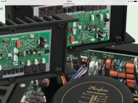
On the other hand Accuphase guys think it's OK
Attachments

On the other hand Accuphase guys think it's OK
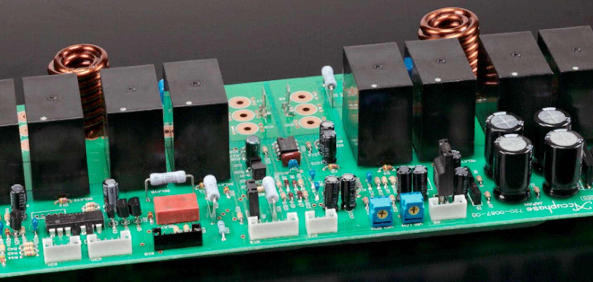
Wow, looks like they use really fat wire on these multi layer coils.
I am guessing it to be 2.4mm. Coil ID about 8mm, OD about 19.5mm and coil height seems to be about 34mm. Looks like 14 to 15 turns. My calculator, estimates this coil at 1uH.
Overall dimensions approx. 34 x 18 x 18 mm
That's pretty massive. Must be for really high power. But then, whats with the Mickey Mouse relay's ?
In post 11 it was said
but he seems unable or unwilling to explain this claim, or clarify if he was really saying something different. Can anyone else help him? Or should we assume that a solenoid is a solenoid, and the only things you get from double-layer are connections at the same end and more stray capacitance?Lazy Cat said:Best to use is two layer inductor, soldered perpendicular to PCB, minimizing the effect of induction currents to the other parts around.
OMG you've still didn't get it, DF96 I'm sure somebody could give you a helpful hand. Just a tip from me: it's very obvious 😉
I don't want to play silly guessing games. I asked a simple question, and you have thus far been unable or unwilling to provide anything other than cryptic clues and veiled insults. Either you want to enlighten me (and, presumably, others) or you don't. Up to you.
In amplifiers made with both TDA2006 (Split supply) and STK series IC's, I used drum coils from ATX power supplies about 50µH @ 5Amper (About 8mm diameter and 12mm height) and all of them working since 10's of years trouble-less.
I've just used the link Mark posted up and it compu RS my inductor at 1.16 uH. I measured it with a hand held inductance meter (200uH range with about 0.2 uH I cannot dial out) and it shows 1.2uH.
Ok result I reckon.
Ok result I reckon.
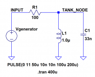
Here is the measurement setup that uses a signal generator + oscilloscope + precision capacitor, to measure an inductor.
I used a Bourns 1.0 uH, 10% inductor and an EPCOS 33nF, 5% capacitor. I connected them on my solderless breadboard, along with a 100 ohm isolation resistor. (You want Risolation to be much much greater than sqrt(L/C), so it doesn't damage the Q of the resonant circuit).
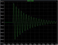
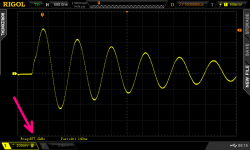
I set the signal generator to produce its largest amplitude square wave at 10 kHz. This should give slightly damped, sinusoidal ringing at the TANK_NODE and indeed, in LTSPICE simulation (2nd image), it does.
Connecting an oscilloscope between TANK_NODE and ground, I got the yellow trace shown below. In theory the frequency of oscillatory ringing should be
_
I used a Bourns 1.0 uH, 10% inductor and an EPCOS 33nF, 5% capacitor. I connected them on my solderless breadboard, along with a 100 ohm isolation resistor. (You want Risolation to be much much greater than sqrt(L/C), so it doesn't damage the Q of the resonant circuit).
I set the signal generator to produce its largest amplitude square wave at 10 kHz. This should give slightly damped, sinusoidal ringing at the TANK_NODE and indeed, in LTSPICE simulation (2nd image), it does.
Connecting an oscilloscope between TANK_NODE and ground, I got the yellow trace shown below. In theory the frequency of oscillatory ringing should be
- fosc = (1 / (2*pi)) * 1 / sqrt(L*C)
- L = (1/C) * (1 / (4 * pi * pi * fosc * fosc))
_
Attachments
Last edited:
To everyone who sent me a PM: yes the yellow tab at bottom left of the scope image in post #38, does indeed indicate that Channel 1 (the yellow channel) has engaged the "B" feature, and that is why there's a B inside a square, on the yellow tab. "B" means "Bandwidth Limit"; I told the scope to limit the bandwidth of Channel 1 to 20 Megahertz. It is displaying a damped sinusoid slightly less than 1 MHz so BW=20MHz is not a tremendously outrageous distortion. It sure does clean up the noise; notice how clean the sinewave appears.
Good eyes!
Good eyes!
However my (more expensive: USD 103!) DE-5000 LCR meter (link) did correctly identify it as an inductor, and did display the correct value: 1.0 uH.
That's the LCR meter I have been eyeballing at eBay.
Did you Mark had any further time check out how well it measures LCR values on their extreme ends and verifying how well it performs in comparison with some pro gears?
- Home
- Amplifiers
- Solid State
- Power Amplifier Output Inductor specification