your lathe wound inductor is too long.
This is because the bobbin you chose is too small in diameter and that resulted in too many turns being required.
Use a bobbin that is MUCH bigger in diameter.
That will reduce the turns required.
Use a wire that is thick enough to be self supporting.
I gave some guidance in post6. I suggest you at least try that and compare to your long skinny inductor.
Hi Andrew,
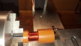
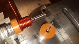
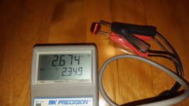
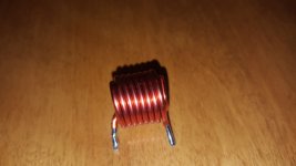
well I was bored and did some coil winding today. I opted for a triple layer coil which gives about 2.6uH right in line as for most application suggested.
Thanks everyone for the discussion. 🙂
Attachments
Dear kct,
The final dimensions and winding details please !
--gannaji
Approx. dimensions are
15mm length
15mm OD
6mm ID
Wire: approx. 1.62mm (AWG14)
Approx. 24 turns (triple layer)
Enjoy. 🙂
when you dont have free space on PCB for inductor or for fear of interference, put it on the speaker terminal together with zobel 😀
Double layer coils are very poor at RF due to self-capacitance (not "stray"). I assume the advantages are that a smaller coil can be used (not just shorter but the turns couple better between them) so fewer turns for a given inductance, and that you have both wire ends at one end, as it were. I'd still recommend single layer coils for audio amps, although I have wound coils into a toroid form before. Not that difficult, actually.
Example: half inch dia coil, 20 turns 1mm wire =20mm long (OK will have to be 0.9mm wire to allow for insulation) then inductance is calculated at 2.7uH, resistance 22mohms; if wound on short coil 10mm long 15 turns (not quite 2 complete layers) gives 2.6uH but resistance is 17mohms.
Capacitance bigger, not calculated.
Last edited:
Double layer coils are very poor at RF due to self-capacitance ... I'd still recommend single layer coils for audio amps ...
Since the output inductor is connected in parallel with a 10 ohm resistor, its self capacitance is negligible at frequencies where the capacitive reactance is greater than 10 ohms. Let us assume that we want the capacitive reactance to be negligible at all frequencies below 1 megahertz. What value of inductor self-capacitance does this imply?
- Xc = 1 / (2 * pi * f * C)
- C = 1 / (2 * pi * f * Xc)
- C = 1 / (6.28E6 * 10)
- C = 16000 picofarads
When I measure double layer inductors of the dimensions given in post #43 (15mm OD / 15mm lengh / 6mm ID), I have never found the self capacitance to be as large as sixteen nanofarads. I would like to ask member John Ellis: have you?
The answer to your rhetorical question is obvious. I think however you miss my point entirely. If I want an inductor I want it to have minimum parasitics, end of story.
If I want an inductor I want it to have minimum parasitics, end of story.
This thread is entitled "Power Amplifier Output Inductor".
If you want a Power Amplifier Output Inductor, what is the benefit of reducing its self capacitance below 16 nanofarads? As you know, a power amplifier output inductor is shunted by a ten ohm resistor.
I like the idea of a toroidal output inductor.
Terminals close together, quite compact, minimum EMI.
Is there a calculator or a formula for this shape ?
Terminals close together, quite compact, minimum EMI.
Is there a calculator or a formula for this shape ?
Last edited:
Thanks everyone for the lively discussion. 🙂
I do understand John's point but really for most amplifier application with inductors of a few turns parasitic capacitance does not seem to matter much.
The triple layer coil I wound seems to resonate at about 10.5MHz, that gives about 90pF parasitic capacitance.
If an amp has the tendency and wants to oscillate at such high frequencies then something is majorly wrong with it that even such coil can't make up for and suppress, I'd say.
I also fabricated a two layer coil as LazyCat #11 suggested which gives 1uH and resonates at about 17MHz.
The dimension are pretty much arbitrarily but it seems as shown in the posted images that some manufacturers feel comfortable to use multi-layer coils in this application. #27 "Accuphase guys think it's OK"
Some points - Grover's inductance book contains a paragraph or two on toroidal shaped coils. L=.004.pi.N^2(R-sqrt(R^2-r^2))-0.004.pi.r.N(G+H) where R is the radius of the main ring, r the radius of the individual coil turns, G=1.25-log(2p/d) where p is the wire pitch and d the wire diameter; H=0.3379-0.6M+0.263M^2 where M=1/N, the number of turns. Dimensions in cm, inductance in uH. Best read the book to check as a lot of the calculations for corrections are in tables.
As an example 30 turns wound on a half inch drill then folded around into a 30mm diameter toroid works out to be 2uH.
When I gave the earlier example of a double layer coil being "more efficient", I should have added that the extra couple of pF or so of self capacitance is unlikely to cause a problem with audio amplifiers. But I would not restrict consideration to 1MHz as Mark implied because modern transistors can give gains well beyond 10MHz. I have no doubt that double layer coils are cheaper as they need less wire, so I can see commercially that is advantageous, but home constructors are generally less concerned about costs.
Last edited:
Yes. Wires at one end only are convenient for PCB mounting. Less wire means less resistance (or you can use slightly thinner wire). Nothing to do with the unsubstantiated claim made by Lazy Cat about less coupling to nearby stuff.john_ellis said:Double layer coils are very poor at RF due to self-capacitance (not "stray"). I assume the advantages are that a smaller coil can be used (not just shorter but the turns couple better between them) so fewer turns for a given inductance, and that you have both wire ends at one end, as it were.
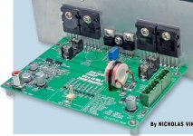
This is SC magazine's design using a standard bobbin.
ULD Mk. II used 6.8uH, then Mk. IV (pic) is 2.2uH keeping the B-field far from the front end and the right-angle gave lower distortion from unwanted mutual coupling.
I thought they also measured lower distortion with bigger 6.8uH value but I can't find that article.
ULD Mk. II used 6.8uH, then Mk. IV (pic) is 2.2uH keeping the B-field far from the front end and the right-angle gave lower distortion from unwanted mutual coupling.
I thought they also measured lower distortion with bigger 6.8uH value but I can't find that article.
Attachments
I'm looking at a power amp module that will only be driving a fairly well behaved bass unit (after an active crossover). It comes with output inductors. Could I just remove them?
If you look at the impedance chart of most speakers, speaker tends to act like inductor at high frequency, too.
The air core inductor value can be even bigger than the value that the calculation suggests. I am talking about around 10uH. It should not effect frequency response too much.
The air core inductor value can be even bigger than the value that the calculation suggests. I am talking about around 10uH. It should not effect frequency response too much.
I thought they also measured lower distortion with bigger 6.8uH value but I can't find that article.
The inductor and the speaker act like a low pass filter. Lower THD with big inductor is expected. (THD are mostly high frequency components)
I'm looking at a power amp module that will only be driving a fairly well behaved bass unit (after an active crossover). It comes with output inductors. Could I just remove them?
Depends on the power amp, if it's class D - no.
For a Class AB amp, the inductor is not even visible in the audio band, so what's the benefit of removing it?
To follow up on the point Bonsai made: Decide your worse case load. Typically the standard used is 8R + 2uF. You can decide whatever matches your application.
The combination of the inductor and the parallel resistor determine peak current in the output devices. The peak current also depends on the bandwidth of the amp, i.e. input filter.
Normally the values of inductor and parallel resistor are juggled to minimize overshoot of an applied square wave whilst also staying within the SOA current of the output devices.
High inductance Values will increase High Frequency distortion.
Using ideal inductors in simulation the effect is quite notable.
Even Low values around 1uH to 2uH
increase distortion
Higher resistor values also create more distortion.
Real life assuming non ideal inductors
Distortion likely to be even higher
Also in real life I have seemed to notice anything larger than 1 uH isn't needed
If you intentionally only capacitive load the amplifier with values from 1n to 220n
And observe square wave ringing/ oscillation.
Minimum Inductor Values from 700n to 1uH tend to stabilize the Amplifier.
Of course their may be excessive Ringing, But without the inductor the amplifier
can burst into hard oscillation instantly.
Obviously in real life a amplifier will never drive 1n to 330n pure capacitive load.
But it shows that very low inductance values are rather effective at stabilizing such a extreme condition
So I would agree with Cordells recommended values only needing to be 500n to 2uH
And personally found 500n to 1uH is all that is needed.
As far as reducing distortion it seems the lower the inductance the better likewise the resistor values.
So 500 to 700n being best for distortion and resistor values from 5 to 3 ohms
- Home
- Amplifiers
- Solid State
- Power Amplifier Output Inductor specification