Just for inspiration:
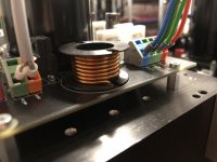
Here is how I did it. I used a plastic bobbin from Epcos B65612B0000T001 and found such a DIY inductor solution has many advantages:
Any number of turns can be realized.
The inductor is mechanically pretty stable and has the optimal form factor (square in side view).
The center may be used for placement of the parallel resistors.
The bobbin is not too expensive and the final inductor looks professional.
I found wiring the inductor challenging using 1.5mm diameter wire and partially broke some bobbins due to high force applied during manufacturing. The resulting inductors with broken bobbin work well but no longer look nice and professional.
Attachments
I want to ask. After you make the inductor, do you measure the actual inductance value? (with LCR meter or some multimeter)
I wonder how accurate those online inductor calculator is.
I wonder how accurate those online inductor calculator is.
I don't have any tools to measure inductance.
The exact inductance is not that important to me.
According to calculation, the inductance of the inductor I made should be 1uH.
In parallel to the inductor I have 5 Ohm.
Together with the R-C shunts at each output stage transistor and the loudspeaker output, the amplifier is surprisingly stable into pure capacitive loads up to 2uF.
BTW: I found an interesting article about output inductor damping: Output Inductors.
It seems to be a good idea to investigate the output network in detail in order to optimize it.
In my case, the damping resistor of 5 Ohms is just a random value, just like the other components. 🙂 Probably I should do a simulation to see whether this makes any sense.
Arthur, you don't reveal where you live so it is a bit difficult to recommend local shops. However, Digikey offers a lot of magnet wire.
Meanwhile I found out that I made up my mind about the whole output network long time ago, but didn't really find a satisfactory solution.
The inductor resonates with the load capacitor unless the damping resistor has very low value. Another way to tame resonance would be to lower the resistance of the loudspeaker side R-C shunt if such a network is present.
Does anybody know how to optimize the output filter(s)?
Is resonance a serious issue?
How low would you go with the damping resistor?
Do you think loudspeaker side R-C shunts are a worthwhile addition? How to optimize such a network?
Attachments
Trying to optimize inductors when using LTSpice is rather tricky because the inductors in LTS don't model 2nd-order effects. By which I mean skin effect and proximity effect. These effects increase the losses as the frequency goes up.
Lee - do you think it might be a better model if the speaker cable were included between the far side of the series L and the load capacitance? Admittedly one would need to guess about the length (and gauge) of the cable but I have the notion that resonance effects might be lower due to losses in the cable.
Lee - do you think it might be a better model if the speaker cable were included between the far side of the series L and the load capacitance? Admittedly one would need to guess about the length (and gauge) of the cable but I have the notion that resonance effects might be lower due to losses in the cable.
Yes, simulation is mostly an approximation and results likely not accurate. However, it is a coarse indicator and super convenient.
Speaker cables are highly complex on their own. I would not know any values to assume here. Cables both present an inductance and capacitance. Fancy audiophile cables may have substantial capacitance and may destabilize amps with sub-optimal output filters.
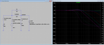
I placed another R-C shunt after the inductor in order to maybe mitigate the effect of fancy cables and loads a bit.
In simulation, this R-C shunt helps to tame resonance caused by the load capacitance a bit.
Bob Cordell wrote a bit about speaker cables and transmission line effects in his book and suggests to properly terminate the cable on the loudspeaker side using a R-C shunt that fits the cable impedance.
I find this idea interesting and consider trying to implement such termination in the speaker cables using Speakon connectors I'm going to build.
Speaker cables are highly complex on their own. I would not know any values to assume here. Cables both present an inductance and capacitance. Fancy audiophile cables may have substantial capacitance and may destabilize amps with sub-optimal output filters.
I placed another R-C shunt after the inductor in order to maybe mitigate the effect of fancy cables and loads a bit.
In simulation, this R-C shunt helps to tame resonance caused by the load capacitance a bit.
Bob Cordell wrote a bit about speaker cables and transmission line effects in his book and suggests to properly terminate the cable on the loudspeaker side using a R-C shunt that fits the cable impedance.
I find this idea interesting and consider trying to implement such termination in the speaker cables using Speakon connectors I'm going to build.
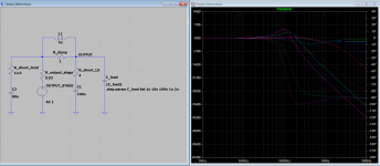
Here is how less resonant filters could look like.
I'm just not sure whether fighting the resonance is a good idea at all.
By lowering the damping resistor of the inductor, the amp get more exposed to the load capacitance.
Lowering the output R-C shunt resistor also subjects the amp to more capacitance at the output, especially with low dampening resistor at the inductor.
Attachments
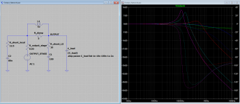
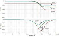
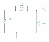
Series Inductor with Speaker load is Basic RL LowPass Filter.
Additional parallel resistor with L will change Slope and Phase.
Basic Model as Shown with R1 changed from 10R , 5R and 3R
Assuming a amp going unstable around 1 to 5 MHz
Seems the filter slope / phase shift of the Higher Resistor Value is more notable.


Additional parallel resistor with L will change Slope and Phase.
Basic Model as Shown with R1 changed from 10R , 5R and 3R
Assuming a amp going unstable around 1 to 5 MHz
Seems the filter slope / phase shift of the Higher Resistor Value is more notable.
Attachments
Pure capacitance loading beyond a few nF is unrealistic. A low inductance, high capacitance, long speaker cable unconnected to the speaker is one scenario. Another is where the inductor in a bass pass crossover saturates. In this case the series resistance of the inductor would mitigate the current requirements.
A more representative situation is to have a load phase angle. 60 degrees has been suggested by some and Audio Precision have a load module with programmable phase angle. This means that there should be a resistive component in the load.
A more representative situation is to have a load phase angle. 60 degrees has been suggested by some and Audio Precision have a load module with programmable phase angle. This means that there should be a resistive component in the load.
You have the end of the coil square against the PCB where is couples most strongly, inducing voltages in the traces under/near it to a maximal degree. If there's only groundplane underneath it forms a shorted turn coupled to the inductor changing he inductance and allowing large ground circulatory currents.The inductor is mechanically pretty stable and has the optimal form factor (square in side view).
Mount cylindrical inductors either on a separate board if you can, or else with the axis horizontal so that less flux cuts the PCB.
The good news is induced voltages and currents from the inductor are linear, the bad news is supply currents coupling direct into the inductor may be very non-linear and increase the distortion noticably.
Hi Mark,
that's a very good point indeed.
In my case I'm lucky to only have the loudspeaker output in this region. On the entry side, there is a plane that goes to the transistors. This overlaps the inductor shape a bit. On the exit side, the signal goes to the loudspeaker terminal and forms another quarter loop adding to the inductor.
However, the NFB take-off point is at the inductor entry, although running perpendicular to the winding.
Would turning the inductor not just change the direction of induction? I guess regardless how the inductor is oriented, it will induce something somewhere.
Maybe an air core toriodal inductor could be the best solution? I thought about this, but didn't find any suitable bobbins.
Solenoids have much stronger field inside than outside, and the mouth of the coil is intermediate in strength, and this dies away rapidly (just like a bar magnet). Ideally we'd simply wind toroidal inductors and have only tiny leakage fields to worry about, but that's trickier (doable with a bespoke 3D printed former I guess).
I haven't heard about the 3D printed former yet.
But this indicates that you were just as unsuccessful finding any ready made toroid air core formers.
It seems like such coil formers do not exists.
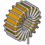
I started research again and considered using pretty much anything toroid shaped as former that is non-ferrous.
The closest match would be distance tubes I found on ebay.
They are for M12 screws with a center diameter of 13mm, up to 25mm outer diameter and variable thickness. I believe 10mm is a good choice. They are made of polyethylene.
I could fit up to 20 turns on such a toroid using 1.5mm diameter wire.
Main challenges would be adding fillets or chamfers to the edges of the toroid and to wind such a strong wire onto such a small toroid.
I haven't calculated inductance yet, but would guess that it takes less than 20 turns to reach 1uH inductance.
Attached is a CAD preview of the finished air core toroid inductor.
But this indicates that you were just as unsuccessful finding any ready made toroid air core formers.
It seems like such coil formers do not exists.
I started research again and considered using pretty much anything toroid shaped as former that is non-ferrous.
The closest match would be distance tubes I found on ebay.
They are for M12 screws with a center diameter of 13mm, up to 25mm outer diameter and variable thickness. I believe 10mm is a good choice. They are made of polyethylene.
I could fit up to 20 turns on such a toroid using 1.5mm diameter wire.
Main challenges would be adding fillets or chamfers to the edges of the toroid and to wind such a strong wire onto such a small toroid.
I haven't calculated inductance yet, but would guess that it takes less than 20 turns to reach 1uH inductance.
Attached is a CAD preview of the finished air core toroid inductor.
Attachments
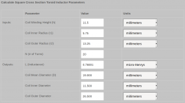
Meanwhile I found this great calculator:
Toroid Inductor Formulas and Calculator - Ness Engineering Inc.
Looks like my DIY toroid would have roughly 0.77uH inductance.
Toroid Inductor Formulas and Calculator - Ness Engineering Inc.
Looks like my DIY toroid would have roughly 0.77uH inductance.
Attachments
Or you could build 3 prototype inductors, having 5, 10, and 15 turns respectively. Measure them on your Der-EE D5000 LCR meter (1% accuracy) and plot measured inductance vs #turns. Interpolate/extrapolate your experimental data to 1.00uH and build a 4th prototype with that many turns. Measure and verify success.
Amazon sells it (link) but usually the price for a new unit is much lower on eBay.
Amazon sells it (link) but usually the price for a new unit is much lower on eBay.
I ordered some plastic rings with slightly different size (12.5mm thick instead of 10mm) and the calculator says this likely gives 1uH straight.
>120$ for a tool I probably need only once in a lifetime is a bit too much. I spent less for my oscilloscope and use this often.
Do you have such a LCR meter?
If yes, I could send inductors to you for measurement.
>120$ for a tool I probably need only once in a lifetime is a bit too much. I spent less for my oscilloscope and use this often.
Do you have such a LCR meter?
If yes, I could send inductors to you for measurement.
Yes I own the DerEE D5000. I also own several other LCR meters with even better accuracy. I'd be happy to measure some inductors for you, free of charge, but ONLY with the agreement that I can keep them after measuring. I absolutely detest the bureaucracy and paperwork that is currently required to ship parcels internationally, so I don't do that any more. If you build two identical inductors, keep one and send me the other, I'll measure it. Then we'll know the inductance of each one since they're identical.
Or if you prefer, build N pairs of inductors, mark them carefully, and send me the female unit of each pair (while keeping the male unit of each pair for yourself). I'll measure the ones you send, and now we'll know the inductance of each pair.
Or if you prefer, build N pairs of inductors, mark them carefully, and send me the female unit of each pair (while keeping the male unit of each pair for yourself). I'll measure the ones you send, and now we'll know the inductance of each pair.
That sound like a good plan.
I will likely calculate some more inductors and send a small variety to you.
I plan to send two of each kind so you cannot only keep them, but also use them for building something if you like.
I'll figure out the paperwork so you hopefully won't have trouble with customs.
It may take a few weeks until all equipment has arrived and I finally can build inductors.
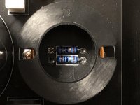
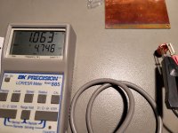
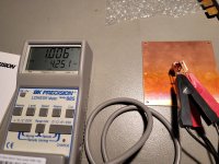
Mark has a point. I went ahead and did some superficial measurements.
The images show the difference with and without a ground plane beneath the coil.
Altho with a measurement frequency of 10kHz the effects are noticeable but perhaps insignificant enough to worry about in this application.
The images show the difference with and without a ground plane beneath the coil.
Altho with a measurement frequency of 10kHz the effects are noticeable but perhaps insignificant enough to worry about in this application.
Attachments
- Home
- Amplifiers
- Solid State
- Power Amplifier Output Inductor specification