Thanks, that is at least interesting in this context.
Rogowski coils typically being used as part of measurement instruments with high input impedance, likely aren't build for high current.
Doing a quick research, I haven't seen any I would like to put on an amplifier output stage PCB.
In case you know suitable Rogowski coils, please share.
Rogowski coils typically being used as part of measurement instruments with high input impedance, likely aren't build for high current.
Doing a quick research, I haven't seen any I would like to put on an amplifier output stage PCB.
In case you know suitable Rogowski coils, please share.
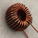
Not to bad! With 30 turns and 2 uH this is definitely an air induktor. For 8-10uH you will need 60-70 turns.
Since people are still suggesting inductors as high as 5uH or even 10uH, I like to bring up Bonsai's excellent paper again:
I had a look through various schematics I downloaded from DIY Audio and indeed, the competent designers use 1uH or less.
Here is some information on the oputput inductor and why its a good idea
Output L_1
You should not need an inductor of more than 2uH - a lot of us are working with about 1 or even a bit less. The actual value required will depend upon how much gain and phase margin your amp has and the worst case capacitive load you are willing to tolerate. The worst case load proposal you will find if you hunt around in the amplifier design literature is 8 Ohms in parallel with 2uF - ESL territory.
I had a look through various schematics I downloaded from DIY Audio and indeed, the competent designers use 1uH or less.
I assumed we were debating class-d output filter inductors with typical values of 10uH. Obviously I was wrong, inductors for linear AB-amps are one order of magnitude smaller, so 1-2uH air core will be fine.
I have seen at least one suggestion that modern ESL's could have equivalent capacitance of 20uF. Not seen any data (not even on ESL manufacturer's spec sheet) to support that though.
And also what frequency response you want your amplifier to have, not just gain and phase margin, though that would be sufficient to assure stability. But if your amp cannot actually drive 2uF at some high frequency gain and PM is a moot point. Unless of course it is bandwidth limited by an input filter etc.
2uF is 4 ohms at 20kHz, 2 ohms at 40kHz etc.
1uH has an impedance of 0.125 ohms at 20kHz, so won't "help" a power-limited amplifier.
Many amps these days can also drive 1 ohm loads, so possibly benefit from small inductors.
There will be a minority of amps that remain stable with a pure 2uF load. That is beyond the normal range and will require special amps specified for such load. Not to mention 20uF....
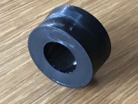
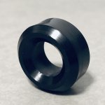
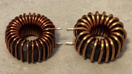
Meanwhile I figured out that the inductor I presented previously has much lower inductance than I thought. I just didn’t put as many turns on the core as planned and don’t see a chance to follow my initial plan. I added two more turns and believe the inductance is between 1.3uH and 1.5uH now.
And I made another inductor with 1.5mm diameter wire, which also has lower inductance than planned. This one was planned to have 1uH and I guess I achieved around 600nH maybe.
And I made another inductor with 1.5mm diameter wire, which also has lower inductance than planned. This one was planned to have 1uH and I guess I achieved around 600nH maybe.
Attachments
Driving ESL’s with heavy capacitive loads is not easy for any amp.
For the stability part of the problem,I always do an AC sim with 2uF to look at the amp performance and ensure there is no peaking (a sure sign of instability) and 1uH in all cases cures it. I always design for >60 deg phase margin ( usually 75+) and >15 dB gain margin. I do on the bench testing with a square wave and a 2.2 uF cap to look foe any signs of instability.
On the power handling side, the second issue here, as mentioned earlier, the load on the amp with a large capacitive load is huge at HF - luckily in most cases there is little musical energy and you can get away with it. Most decent modern amps use oversized OPS (the devices are cheap!) so you can back off on the intrusive load line shaping protection or dispense with it completely.
Last edited:
Hi Bonsai,
What frequency do you use for square wave testing? And is this full power testing? What loads?
What frequency do you use for square wave testing? And is this full power testing? What loads?
I usually use 2-3 kHz and at about 1V pk-pk for stability testing.
For high power testing, I use a sine wave, although with the nx-Amp, I did test at c. 100 kHz full power with a square wave. That is a truly brutal test for an amplifier.
For high power testing, I use a sine wave, although with the nx-Amp, I did test at c. 100 kHz full power with a square wave. That is a truly brutal test for an amplifier.
Thanks Bonsai.
This is one of those areas I've been curious about. A lot of the stuff I tinker with in the wonderful world of simulations looks good with the specs you mentioned, but gets harder to tame with a full power 100 kHz square wave into 4 ohms. Which made me wonder if if a test that brutal has any merit.
This is one of those areas I've been curious about. A lot of the stuff I tinker with in the wonderful world of simulations looks good with the specs you mentioned, but gets harder to tame with a full power 100 kHz square wave into 4 ohms. Which made me wonder if if a test that brutal has any merit.
- Home
- Amplifiers
- Solid State
- Power Amplifier Output Inductor specification