90scaraudio,
That helps. Thank you.
Do you have any links or resources you'd recommend for choosing power supply fuse values? I've read that they need to be determined by both the output and speaker load, as well as the VA rating of the power transformer. I'm using an SMPS so I'm not really clear on how to determine values.
Thank you for your detailed posts. They're very helpful.
Best wishes - z
Last edited:
Just remove the fuse and clip in your amp meter, check the bias or set bias. I don't know the fuse value. These could also add some limits if something went wrong. Somebody will chime in.

No rail fuses on this one, just a main fuse. I measure bias across the emitter resistor than do the math.
The LJM MX50SE and LJM L12-2 are very good sounding amps. I've built both. I'm using a 18-0-18 300VA Toroid on the MX50SE because of SOA of some of the semiconductors. Very good amp.
Well with the possiblity of fake parts, I'll use rail fuses and feel the need for protection. No need for math for when substituting amp meter for fuse. Everyone has different ideas. Not looking for conflict.
Oh No! I agree with you that doing it that way is perfect. I normally use PS boards that have rail fuses just not this amp. I've used these...LJM Rectifier filter Power Supply Board With speaker protective for Amplifier.
https://www.ebay.com/itm/124866209962
https://www.ebay.com/itm/124866209962
Super Cool! I was not aware of these boards and would be a great addition to my amps. Thanks for the info...Did you replace any parts in your kits or did you use all the parts provided? Any problems yet? Thx for sharing your experience.
Only added multi turn pots for bias adjust and used audio grade caps where I could. Other wise, I used everything in the kits.
I'm using an old stereo pwr amp which will have +/-45VDC . and will build to the stock design. A yr ago I had built the MX50 and was very pleased, no problem, nice sound but not 4ohm capable. The speakers I have now are 4ohm. Not sure how long it will take to arrive?
Kit arrived, looks nice. The electro's have higher voltage ratings (good). I'm missing 1 cap (105). I believe it's .1 100v. I'm using an old Peavey chassis (stereo amp Model M-2600) that has all the parts I need. I'll get some pics as I proceed. My boards are green and have the panda stamp from China audio on Ebay.
"CORRECTION=FOUND THE LITTLE CAP" My fault it was like magic!Kit arrived, looks nice. The electro's have higher voltage ratings (good). I'm missing 1 cap (105). I believe it's .1 100v. I'm using an old Peavey chassis (stereo amp Model M-2600) that has all the parts I need. I'll get some pics as I proceed. My boards are green and have the panda stamp from China audio on Ebay.
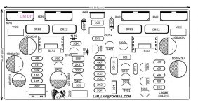
Of course, maybe it's just my design. Not ideal.I bought one on aliexpress and also tried to solve the puzzle. What I found is identical except for one detail: I can't find the 33k resistor between VEE and the base of the 2N5401pre-driver: your schematic counts 29 resistors, the actual board only 28. (at least, the version I received).
So if anyone is interested. Try to improve it. And get the result.
This website is full of unrealistic measurement data. It's even completely out of range.
I don't expect the best performance. But there must be. Real performance. Test data.
It doesn't mean good or bad.
In practical application, it is possible to use 10uF instead of 105 capacitor, which is no problem.
But if there is no 33K resistance. It must be a fake.
Attachments
It should be 106. Use 50v10uf BP capacitor. PCB in 2021 and 2022 are not exactly the same.Kit arrived, looks nice. The electro's have higher voltage ratings (good). I'm missing 1 cap (105). I believe it's .1 100v. I'm using an old Peavey chassis (stereo amp Model M-2600) that has all the parts I need. I'll get some pics as I proceed. My boards are green and have the panda stamp from China audio on Ebay.
50v10uf bp=106 capacitor was used in 2022, but this is not important. It doesn't matter.
The reason is that I found yellow ceramic capacitor suppliers. This capacitor may be damaged by 10%.
So I replaced the black capacitor
My boards have 2 105 caps (you say yellow ceramic ,1)... Now should be 10uf 50v Bp... Should I replace both caps with new10uf/50v BP? Your reply is very helpful !
CRAP !! When tapping 3mm holes in my heat sink.. MY tap broke off. So it set me back 10 days while the new taps arrive. I need to be more careful.
This capacitance has no effect. You can ignore it.My boards have 2 105 caps (you say yellow ceramic ,1)... Now should be 10uf 50v Bp... Should I replace both caps with new10uf/50v BP? Your reply is very helpful !
It's just that there was a problem with the capacitor later. Nominal 106. I changed it to 50v10uf
105 do not replace.
Pay attention to safety. L20se has very little fever. So it's easy to install.
Greetings, Amp builders. So there are 2- 105 yellow ceramic caps. Which have been changed to be 106. What did you use for 106? Sorrry for being so thick headed... Are both replaced since the ceramic caps have problems?
yes. In fact, this is not very important.Greetings, Amp builders. So there are 2- 105 yellow ceramic caps. Which have been changed to be 106. What did you use for 106? Sorrry for being so thick headed... Are both replaced since the ceramic caps have problems?
Because I later found a 106 ceramic capacitor. I measured its performance.
It is better than 105. Lower esr. So I changed the PCB to 106
But later I found that 10% of 106 ceramic capacitors will break down in use. Damage.
No way out. I have to use 50V 10uF BP capacitor instead.
In fact, this does not affect anything. As long as there is no quality problem with any capacitor.
Will not affect the performance.
- Home
- Amplifiers
- Solid State
- Power Amplifier LJM L20SE