LJM L20SE 2004-2018
Just starting to build a pair of these. I'm using a 30-0-30 300va toroid and one or maybe two Rectifier Filter Power Supply Board w Speaker Protection 4x50V/6800UF on each board.
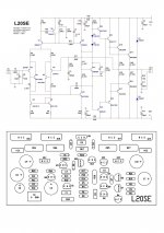
One question about multi turn pot for bias control. I've built the MX50SE and did the bias pots...glad I did. On the L20SE boards I received, R-17 is 8.2k and C-4 and C-8 are 10uf/50v NP.
Do I leave out the 8.2k and put in a 10k multi-turn? That's what I did on the MX50.
Older home audio amplifiers have a bias pot and I'm comfortable doing any mods to make this as nice sounding as possible.
Any help would be very much appreciated before I get too far along with the build.
Just starting to build a pair of these. I'm using a 30-0-30 300va toroid and one or maybe two Rectifier Filter Power Supply Board w Speaker Protection 4x50V/6800UF on each board.
One question about multi turn pot for bias control. I've built the MX50SE and did the bias pots...glad I did. On the L20SE boards I received, R-17 is 8.2k and C-4 and C-8 are 10uf/50v NP.
Do I leave out the 8.2k and put in a 10k multi-turn? That's what I did on the MX50.
Older home audio amplifiers have a bias pot and I'm comfortable doing any mods to make this as nice sounding as possible.
Any help would be very much appreciated before I get too far along with the build.
Attachments

...One question about multi turn pot for bias control. I've built the MX50SE and did the bias pots...glad I did. On the L20SE boards I received, R-17 is 8.2k and C-4 and C-8 are 10uf/50v NP.
Do I leave out the 8.2k and put in a 10k multi-turn? That's what I did on the MX50....
Any help would be very much appreciated before I get too far along with the build.
You're right. R17 should be around 9k. But be careful: The bias current is very sensitive to change of R17. Maybe it is better to put 1k (fixed or pot) in series with 8k2 ... I did this and the bias current became about 30 mA ...
Attachments


Question... The kits I received are using NP 10uf electrolytic caps for C4 and C8. Not much room there! The schematic posted by Eliseu shows a 1uf in these locations. So my Question is.. OK to use 1uf Metallized Polyester Film Capacitor in C8 location? It sure would fit better.
Thanks all
Thanks all
Question... The kits I received are using NP 10uf electrolytic caps for C4 and C8. Not much room there! The schematic posted by Eliseu shows a 1uf in these locations. So my Question is.. OK to use 1uf Metallized Polyester Film Capacitor in C8 location? It sure would fit better.
Thanks all
It seems to me you have a younger version of the kits. The driver transistors also differ: 2SA1659A / 2SC4370A vs 2SA1943 / 2SC5171. Both pairs are perfect replacements for each other. Because both Eliseu and myself are very satisfied with the quality of our amps, and the rest of the schematics hardly differ, I think you can choose 1 µF for C4 and C8 without any problem...
Thanks, I'll leave C4 alone and change C8 to 1uf.
One more Q?
LJM mentions it's OK to use less then +-60v rails and I've got an Onkyo adm21 that I was thinking on using the chassis, heatsink, and transformer. The transformer has 43-0-43, 33-0-33 (not used), 18-0-18, and 5vac. The schematic for this amp shows +-57.8 rails and it uses 2sc5200, 2sa1943 (just one of each for each channel.
Is the L20SE going to live with this much rail voltage?😕
Attachments
It seems to me you have a younger version of the kits. The driver transistors also differ: 2SA1659A / 2SC4370A vs 2SA1930 / 2SC5171. Both pairs are perfect replacements for each other. Because both Eliseu and myself are very satisfied with the quality of our amps, and the rest of the schematics hardly differ, I think you can choose 1 µF for C4 and C8 without any problem...
I see the A1939 and C5171 have double the fT @ 200 MHz... I can get these from Bonanza :: Find everything but the ordinary and are said to be Toshibas... Is it worth getting these or just use the ones with the kit?
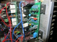
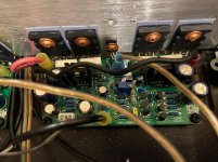
10 ohms 1 w resistor near the output was smoked. Amp still working.
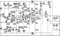
What is the function of this resistor 10 ohms 1w and and condentaror 100nF?
The R28/C11 form a Zobel network (the R28 10 Ohm approximates to the expected loudspeaker load impedance and the C11 capacitor is invariably 100 nF) to mitigate amplifier high frequency instability due to loudspeaker voice-coil inductive reactance.
See the full LJM L20SE Design Notes at my other post: https://www.diyaudio.com/forums/solid-state/199093-l20-amp-njw0302g-11.html#post6469950
JA
I see the A1939 and C5171 have double the fT @ 200 MHz... I can get these from Bonanza :: Find everything but the ordinary and are said to be Toshibas... Is it worth getting these or just use the ones with the kit?
You don't have to look for 1930, 5171
Because I tested it on APSYS 2722 with 1659a.
He's distorted. The performance is as like as two peas. The accuracy is 0.0001%.
And now 1930 5171 has stopped production. It's very possible to buy fake goods.
So. Don't buy it, replace it. meaningless.
Olá!
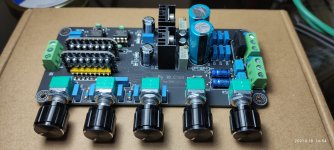
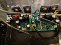
Fotos da última atualização. Adicionados fonte com diodo schottky e pré amplificador com controle tonal.
-----------------------------------------------------------------------------
Hi!
Photos from the last update. Added source with schottky diode and preamp with tonal control.
Fotos da última atualização. Adicionados fonte com diodo schottky e pré amplificador com controle tonal.
-----------------------------------------------------------------------------
Hi!
Photos from the last update. Added source with schottky diode and preamp with tonal control.
Attachments

One big important thing here - a 2N5551 for the VAS at 50V supplies ? It is going to run incredibly hot. If the Zobel is getting smoked, it's unstable. Those 1N4148 diodes in the VBE stage are in the wrong place, and probably a bad idea anyway.
One big important thing here - a 2N5551 for the VAS at 50V supplies ? It is going to run incredibly hot. If the Zobel is getting smoked, it's unstable. Those 1N4148 diodes in the VBE stage are in the wrong place, and probably a bad idea anyway.
Dear,
This class AB amplifier project and its variations is already extremely widespread on the internet and in several books, such as "Douglas Self in Audio Power Amplifier Design". Because the project is powered by +/- 50v, it does not mean that a certain block is also and not even the current is the same. The VAS circuit is correct and the current flowing through it is sufficient for the 2N5551 to work. The two 1N4148 diodes are a complement to the BIAS block with the 2SD669A.
The focus of this project is not power, the focus is fidelity and low distortion.
----------------------------------------------------------------------------------
Prezado,
Este projeto de amplificador classe AB e suas variações já é extremamente difundido na internet e em vários livros, como por exemplo "Douglas Self em Audio Power Amplifier Design". Por o projeto ser alimentado por +/- 50v não significa que um determinado bloco também seja e nem mesmo a corrente seja a mesma. O circuito de VAS está correto e a corrente que passa por ele é suficiente para o trabalho do 2N5551. Os dois diodos 1N4148 são um complemento para o bloco de BIAS com o 2SD669A.
O foco desse projeto não é a potência, o foco é a fidelidade e baixa distorção.
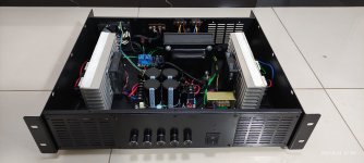
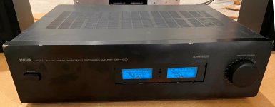
L20SE in a Old Yamaha DSP-E1000 Chassis
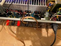
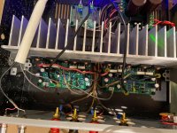
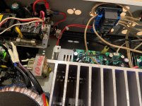
I finally had a little time to complete one more project. I found this Yamaha on Ebay for $36 shipped and yes, it's been through the ringer!!
I used the volume pot (100k) for input level and wired it following ESP audio website diagrams. Works very well.
For the momentary on/off, I used an Arduino Nano to do the work of the power relay circuit and light up LED's. I used the 11vac transformer, part of the power relay circuit, to feed power to a Power Supply Module 3.3V/5V for Arduino Boards. This also works perfect.
I ended up using the Yamaha 25-0-25 vac transformer 400va. After the bridge rectifier and filter it has +/- 30vdc.
I used the stock heat-sink.
I had an old VU meter that just happens to fit well into the face of this thing.
I replaced the 8.2k resistors on the L20SE and installed 10k multi-turn pots.
I set bias by touching one lead of my multimeter to the emitter of one output transistor and the other lead to speaker out and set it to 1.5 millivolts. It has the 0R1 5 watt emitter resistors. So if my thinking is correct, that should be 15 milliamps per transistor. 30 per pair.
It works and sounds very good for what it is.😀
Attachments


I finally had a little time to complete one more project. I found this Yamaha on Ebay for $36 shipped and yes, it's been through the ringer!!
I used the volume pot (100k) for input level and wired it following ESP audio website diagrams. Works very well.
For the momentary on/off, I used an Arduino Nano to do the work of the power relay circuit and light up LED's. I used the 11vac transformer, part of the power relay circuit, to feed power to a Power Supply Module 3.3V/5V for Arduino Boards. This also works perfect.
I ended up using the Yamaha 25-0-25 vac transformer 400va. After the bridge rectifier and filter it has +/- 30vdc.
I used the stock heat-sink.
I had an old VU meter that just happens to fit well into the face of this thing.
I replaced the 8.2k resistors on the L20SE and installed 10k multi-turn pots.
I set bias by touching one lead of my multimeter to the emitter of one output transistor and the other lead to speaker out and set it to 1.5 millivolts. It has the 0R1 5 watt emitter resistors. So if my thinking is correct, that should be 15 milliamps per transistor. 30 per pair.
It works and sounds very good for what it is.😀
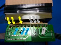
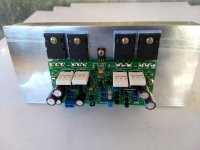
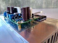
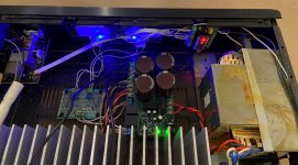
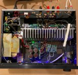
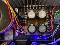
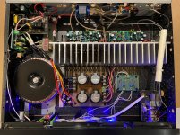
I decided to change the power supply to a 30-0-30 400va toroid. I've also change the filter cap's to 10,000uf/63v types. Had to add a small 10vac transformer to power a speaker protect module. The rails are know +-46vdc. I also put back the 8.2k bias resisters but put a 5k multiturn pot in series with them. I've adjusted the bias to 45mA per pair. (thats 4.5mV with 0R1 ohm emitter resistors). It really brought out the sound. Huge improvement!! Everything is staying cool... Very nice amps for the cost😀
I decided to change the power supply to a 30-0-30 400va toroid. I've also change the filter cap's to 10,000uf/63v types. Had to add a small 10vac transformer to power a speaker protect module. The rails are know +-46vdc. I also put back the 8.2k bias resisters but put a 5k multiturn pot in series with them. I've adjusted the bias to 45mA per pair. (thats 4.5mV with 0R1 ohm emitter resistors). It really brought out the sound. Huge improvement!! Everything is staying cool... Very nice amps for the cost😀
Attachments
Hi friend.Además, debe prestar atención a los bienes reales. Y productos falsos.
En caso de falsificaciones. Por favor envíeme un correo electrónico LJM_LJM@foxmail.com [/correo electrónico]
To use a voltage of +-66V, what components do I need to change?
Thank you.
All is not problem , great designI had a quick look at the circuit.
- What is the phase and gain margin?
- Where is the short circuit protection?
- HDS662 has to temperature compensate 6 VBE's
- current source with 270 Ohm resistor and 2N5401 will not be stable with severe ambient temperature changes!
- where is the offset-null trimming?
- where is the quiescent current trimming?
- 1n4004 are not very fast diodes for freewheeling transients!
- 1mF capacitor in the feedback path ?
Hi 90scaraudio,I decided to change the power supply to a 30-0-30 400va toroid. I've also change the filter cap's to 10,000uf/63v types. Had to add a small 10vac transformer to power a speaker protect module. The rails are know +-46vdc. I also put back the 8.2k bias resisters but put a 5k multiturn pot in series with them. I've adjusted the bias to 45mA per pair. (thats 4.5mV with 0R1 ohm emitter resistors). It really brought out the sound. Huge improvement!! Everything is staying cool... Very nice amps for the cost😀
Do you find that the increase in voltage was essential to the improvement in the quality of sound? Could I just get away with only increasing the bias? I have an SMPS at +/-36v and would like to use it. Thank you - z
I was using the stock tranny in the stereo and it was a little low on volts. That's why I put the toroid in there. I know that the bias should be set to about 40mA per pair as long as the rail voltage is with in tolerance to LJM's design. Hope it helps.Hi 90scaraudio,
Do you find that the increase in voltage was essential to the improvement in the quality of sound? Could I just get away with only increasing the bias? I have an SMPS at +/-36v and would like to use it. Thank you - z
- Home
- Amplifiers
- Solid State
- Power Amplifier LJM L20SE