hiii alllll
wowwwwwwwwwwwwwwwwwwwwwwww
i finalllllly test my amp 🙂 ...
do u remember me ? i posted some photos of my incomplete amp , finally i got a chance to finish and test my amp this days , and i just turn it on for the first time , i test it for a few mins , and it s JUST GREAT ! ,
i ll test it completly and will post some photos as soon as i can ,
just wanna say , thanks a lotttttt quasiii 🙂
I have build quasi amplifier with bipolar output. Amp is working very good about two months without any problems.
What is the max +/-Vcc for four pices of MJ15024 per rail
Sorry for my bad english
What is the max +/-Vcc for four pices of MJ15024 per rail
Sorry for my bad english
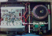
Wha does this do?
Tell us more. Looks very good. Is this
"a" quasi amplifier or is this "QUASI's AMPLIFIER"?
Shawn.
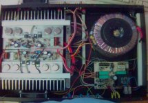
kraft said:Pic of finished amp
Tell us more. Looks very good. Is this
"a" quasi amplifier or is this "QUASI's AMPLIFIER"?
Shawn.
Attachments
bigpanda said:Hi Kraft,
Kind enough to show the schematic? Tks
bigpanda,
I suspect Kraft used the schematic or based it on the one quasi posted in Post #353:
http://www.diyaudio.com/forums/showthread.php?postid=822751#post822751
and the schematic link in the post was:
http://www.diyaudio.com/forums/attachment.php?s=&postid=822751&stamp=1137818325
I am not sure if quasi ever started a thread on this BiPolar output device varient of his excellent MOSFET version that this thread is about.
Regards,
John L. Males
Willowdale, Ontario
Canada
22 June 2006 23:04
This is QUASI's AMPLIFIER
Yes i used shematic in post 353
more pics http://kraft.moj-album.com/album/3690118/
PCB and schematic http://www.esnips.com/web/KRAFTsBusinessFiles
Yes i used shematic in post 353
more pics http://kraft.moj-album.com/album/3690118/
PCB and schematic http://www.esnips.com/web/KRAFTsBusinessFiles
Ahmad_tbp said:hiii alllll
wowwwwwwwwwwwwwwwwwwwwwwww
i finalllllly test my amp 🙂 ...
do u remember me ? i posted some photos of my incomplete amp , finally i got a chance to finish and test my amp this days , and i just turn it on for the first time , i test it for a few mins , and it s JUST GREAT ! ,
i ll test it completly and will post some photos as soon as i can ,
just wanna say , thanks a lotttttt quasiii 🙂
Well done Ahmad, well done indeed. You are truly dedicated to DIY. I look forward to the photos.
kraft said:I have build quasi amplifier with bipolar output. Amp is working very good about two months without any problems.
What is the max +/-Vcc for four pices of MJ15024 per rail
Sorry for my bad english
Another great effort Kraft. I am only halfway through this PCB and to see yours is great because now I will use some of your ideas. There are some things about your layout I would like to explore and develop, so maybe we should start a new thread.
Any thoughts from followers of this thread, moderators ?
Cheers
quasi said:
Another great effort Kraft. I am only halfway through this PCB and to see yours is great because now I will use some of your ideas. There are some things about your layout I would like to explore and develop, so maybe we should start a new thread.
Any thoughts from followers of this thread, moderators ?
Cheers
Quasi,
I think it is almost 6 of one half a dozen of other to start a new thread about the BiPolar varient. I favour a seperate thread on the premis that there will be some unique elements to the BiPolar design and this thread is basically well engrained with the MOSFET version. While I am sure many of the same questions may arise about the input section, the driver section is different as is the heatsinking. I suspect a seperate thread is good for those that are bias (pun intended) to liking BiPolar designs more so than MOSFET designs.
Just my thoughts to consider with those that provide you input on your question to or not to start a new thread for the biPolar varient. Besides when you introducted the BiPolar schematic to this thread you said you start a new thread for that varient.
Ok, I have said my piece. Let the flames begin! 😉
Regards,
John L. Males
Willowdale, Ontario
Canada
23 June 2006 14:15
We should start a new thread for bipolar amp
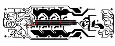
For drawing PCB i have speed 3 to 4 hours and there is a little mistake capacitor C5 is missing
For drawing PCB i have speed 3 to 4 hours and there is a little mistake capacitor C5 is missing
kraft said:I have build quasi amplifier with bipolar output. Amp is working very good about two months without any problems.
What is the max +/-Vcc for four pices of MJ15024 per rail
Sorry for my bad english
Onsemi only publish a DC SOAR for the MJ15024 so I can only estimate it's 100mS SOAR which is more relevant for music signals. Even so the MJ15024 is quite a strong transistor and it's SOAR is similar to most transistors with this power rating (interestingly at 100v an MJ15003 is stronger).
With 4 devices per rail (8 per amp board) I would not go above +/- 75v for safe operation into a nominal 4 ohms impedance.
Cheers
New Bipolar Qausi
Qausi, if you have the time to dedicate, do it, start a bipolar thread. It would be a different amp. Cousin? Sister? Brother of Quasi?
Good Times,
Shawn.
Would it be scalable in power like the Hexfet? It is so nice to have options.
quasi said:...so maybe we should start a new thread. Any thoughts from followers of this thread, moderators ?
Cheers
Qausi, if you have the time to dedicate, do it, start a bipolar thread. It would be a different amp. Cousin? Sister? Brother of Quasi?
Good Times,
Shawn.
Would it be scalable in power like the Hexfet? It is so nice to have options.
Here we go again or Brother of Quasi !
A new thread on the bipolar version seems the way to go. My initial thoughts are;
- the existing mosfet PCB has potential for conversion to a TO3P / TO247 bipolar amp with the addition and changes to a few components.
- another PCB (one I have started) will be developed to take TO3 devices.
- as Shawn has suggested it will be scalable in power.
- it will require good contribution from other members.
- the new thread will provide an opportunity for those who build both versions to compare bipolar v mosfet.
- comments about complimentary amps will be frowned upon 🙄
Cheers
Hi,
I assume complimentary comments will be acceptable, but only when the BJT quasi is up and running in it's new thread.
I assume complimentary comments will be acceptable, but only when the BJT quasi is up and running in it's new thread.
PCB return Wire
Hi,
I was just loving to hate the wire under the PCB😉 Could the common trace be split in two forming an open center to hold the trail of what exists as a "wire" in the current board layout? I put this together in a second in photoshop so please excuse the roughness. Just wondering if the concept is acceptabe?
Shawn.
Attachments
Quick question here: would the IRFP460A's be worth the extra expense, over the 450's? Or are they even suitable in the first place?
PM650 said:Quick question here: would the IRFP460A's be worth the extra expense, over the 450's? Or are they even suitable in the first place?
Hi PM650,
In theory most IRF MOSFETs will be fine alternates. Of cource you have to be mindful of the power handling ability and voltage rating of the device for the desired amp power level you wish.
Based on my review of the datasheets between the IRFP450 and IRFP460A I would suggest the IRFP460A would be a very good alternate on a few counts. The IRFP460A has higher power/amp handling ability, respectable rise/fall times and in my opinion a better Ciss behaviour.
The IRFP460A (at 70C Tc) handles 180W, whereas the ther IRFP450 handles 123W. This means you will have a much greater safety margin and lower operating temperature using three of the IRFP460A's in quasi standard three pair module design. This is not the only aspect to calculate, there is Ic calculations as well. I do a number of different calculations to determine suitability, power handing and number of devices.
If you read back through earlier posting of this thread you will find how quasi calculates the a safe power handling of a device for Tc=50C. One example Post #116:
http://www.diyaudio.com/forums/showthread.php?postid=533712#post533712
This means according to the "quasi" calculation (280W X 2) X 30% = 168W a pair of IRFP460A.
Some have have an interest in just a single pair version. I would suggest the IRFP460A in a single pair design would handle 90W/180W at 8/4 ohms. From there you can scale your power needs from there. I wish those devices where available locally as they seem to be a very good alternate choice to the IRFP450.
You may also want to refer the the quasi chart for number of devices for desired output power level for a target impediance. It is important you read the thread to find out the comments and assumptions of the chart and related calculations for power handing of output devices other's have considered/used. The "quasi" chart was posted initially Post #285:
http://www.diyaudio.com/forums/showthread.php?postid=794932#post794932
A few postings back the "quasi" chart was discussed a bit again, Post #640:
http://www.diyaudio.com/forums/showthread.php?postid=945181#post945181
Regards,
John L. Males
Willowdale, Ontario
Canada
26 June 2006 03:00
HI !
Hi Quasi,
It seems I am guilty for bipolar thread
don't shoot me !
Just put note on this thread, thanks.
By the way , I made 8 pow. amp with 6 Fets per Ch. , very god Amp. for little money .Sound nice . With 1 amp I, drive 4 Boxes
15"+ horn (Elektro Voice) per box . But for cooling I, used 80x80 fans, per Ch. in same case.
Don't forget , note me !
- Home
- Amplifiers
- Solid State
- Power amp under development