Re: Balanced input for Quasi
Hi Shawn,
It has been a few months since I looked into the options and circuits one can use for balanced inputs and outputs. You are certainly not restricted to using OpAmps only. As I am sure you will become aware there are discrete, OpAmp and Tube versions of balanced line drivers. There is a following that suggests the transformer based versions are better, but I cannot say as I am not even close to knowledgeable enough to figure that out as yet.
I did make one suggestion related to Balanced inputs to Miodrag in my Post #549:
http://www.diyaudio.com/forums/showthread.php?postid=927348#post927348
you may want to look at if you have not already.
I am glad there are others like you and a few others using quasi's amp wishing to include balanced line drivers. To me it makes perfect sense. I for one would like to hear what you settled on and why for a balanced line driver. I also like to hear what others have decided on as an add on circuit to quasi's amp.
I suspect I will use a balanced line driver not based on a transformer due to cost and availability of the transformers.
Regards,
John L. Males
Willowdale, Ontario
Canada
02 July 2006 17:16
TomWaits said:I discovered Jensen Transformers in my search for parts to give my Quasi a balanced input. Then I read some of their schematics and I just added this on to the circuit. Can a balanced input be added this way? Or should it be done with an opamp? Or are there are other solutions?
I think RCA and Balanced is what I need because this amp ( like everything I make) may be used Pro or consumer.
Cheers, Shawn.
The Jesen transformer part # JT-10KB-D?
Hi Shawn,
It has been a few months since I looked into the options and circuits one can use for balanced inputs and outputs. You are certainly not restricted to using OpAmps only. As I am sure you will become aware there are discrete, OpAmp and Tube versions of balanced line drivers. There is a following that suggests the transformer based versions are better, but I cannot say as I am not even close to knowledgeable enough to figure that out as yet.
I did make one suggestion related to Balanced inputs to Miodrag in my Post #549:
http://www.diyaudio.com/forums/showthread.php?postid=927348#post927348
you may want to look at if you have not already.
I am glad there are others like you and a few others using quasi's amp wishing to include balanced line drivers. To me it makes perfect sense. I for one would like to hear what you settled on and why for a balanced line driver. I also like to hear what others have decided on as an add on circuit to quasi's amp.
I suspect I will use a balanced line driver not based on a transformer due to cost and availability of the transformers.
Regards,
John L. Males
Willowdale, Ontario
Canada
02 July 2006 17:16
ilimzn said:Regarding the Ciss and Crss issue
Ilimzn,
can you help me to finally get it?
For a "complementary" driver to Mosfet follower output stage:
the total current need is determined by Crss times the number of devices in parallel, plus Ciss times 1 / (Gm * Rload) ?
Total input capacitance of the output devices seen by the driver is the summation of these numbers for N- and P-stage ?
Does the transconductance value not have to be corrected for source resistors, Gm`= Gm / (1 + Gm x Rs) ?
The old lateral mosfets had a Gm (Yfs) of 1 S.
Vertical devices have Gm values that are much higher, e.g. 6 for an IRF350 or 8 for your beloved IRFP9140. I take it that makes vertical mosfets easier to drive by a driver compared to lateral devices ?
I agree with AT, having the mosfet ins and outs for different topologies gathered in a single thread would be very enlightening. I'm passing on corrections by others after discovering i've been running around for years with the wrong answer, to find out it's again not the full true story either.
Thanks for your tuition, very instructive as usual.
hello i downloaded all the things in heer can you please tell me
how many w have this power amplifier and wich is the corect scheme and silkscrean and what power suply will be the best
sorry for my pour english
Regards
how many w have this power amplifier and wich is the corect scheme and silkscrean and what power suply will be the best
sorry for my pour english
Regards
Quasi's PDF
Quasi made a PDF with everything you need inside. I posted it on the net. Here is the link if you have not downloaded this
Look at that PDF as it may answer many of your questions.
Cheers,
Shawn.
vicelord said:hello i downloaded all the things in heer can you please tell me
how many w have this power amplifier and wich is the corect scheme and silkscrean and what power suply will be the best
sorry for my pour english
Regards
Quasi made a PDF with everything you need inside. I posted it on the net. Here is the link if you have not downloaded this
Look at that PDF as it may answer many of your questions.
Cheers,
Shawn.
Come back again
Please don't forget to tell us about your progress if you decide to build Quasi's amp.
Shawn.
vicelord said:thanks alot for the pdf it answered all my questions
regards
Please don't forget to tell us about your progress if you decide to build Quasi's amp.
Shawn.
i wont forget
today i am going to buy some tranzistors
but my progress will be slow because the parts ar very expansive in my country
Bogdan
today i am going to buy some tranzistors
but my progress will be slow because the parts ar very expansive in my country
Bogdan
Hello again and sorry for duble posting
today i wordered the pcb's
very expensive i saw a price lice from the us in wich this amplifier iti made with 84$ it is true???
one pcbcosts abaut 5dolar or a little bit more
what kind of transformer showd i use hau much power he will need for running in 8ohms??
how much capacitors showd i put they are expensive two so please by gentil
REgards
The $84 question
Yes it is true, I built by amp for around $80, but I mostly used second hand parts and I made the PCB's myself. I also cut the heatsinks, fabricated the case and re-wound a second hand transformer.
It can be done but it takes a lot of extra effort plus searching for junked electronics as a source of components.
I used a 500va transformer with AC voltages of 53 0 53 volts. This gave me DC rails of +/- 73 volts.
My amp delivers about 210 watts into 8 ohms and about 360 into 4 ohms (single channel driven).
I think more powerful versions have been built, Shawns for example could probably drive into 2 ohms delivering a lot more power.
Maybe other builders could post details of their power supply and amp configuration with the powers they achieved.
Cheers
Quasi
vicelord said:how much capacitors showd i put they are expensive two so please by gentil
It depends on your voltage rails and the load. For a 150 watt amp into 8 ohms 10,000uf per rail is the minimum I would use. If you want to run the same amp into 4 ohms then closer to 20,000uF would be better.
You will still get pretty good results with less though, remember most consumer grade amps use a lot less than this.
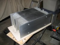
By the way Shawn, nice case.
Cheers
vicelord said:Hello again and sorry for duble posting
Post away and don't hold back, I don't 😉
quasi said:By the way Shawn, nice case.
You should see it tonight. I'm wiring it up

Shawn
Re: Re: Balanced input for Quasi
I think I'm now set on some very high-end ADI or BurrBrown OpAmps mounted on tiny PCBs soldered to the rear of the XLR connector. I'll strip some of the input circuitry off the PCBs for each channel and hook it direct. No RCA, just XLR. I can get the OpAmps for free but the Jensen XFMRs would set me back more dollars, just as you indicated.
This will happen later. For now I need to stick to the plan and get the wicked thing rocking😀 Later I'll use the hole where the rca is mounted to pull my knock-out through for the XLR. Thanks again for the source material. You would make a lot of money if you were a librarian or a research analyst😉
Shawn.
keypunch said:Hi Shawn,
It has been a few months since I looked into the options and circuits one can use for balanced inputs and outputs. You are certainly not restricted to using OpAmps only.
I think I'm now set on some very high-end ADI or BurrBrown OpAmps mounted on tiny PCBs soldered to the rear of the XLR connector. I'll strip some of the input circuitry off the PCBs for each channel and hook it direct. No RCA, just XLR. I can get the OpAmps for free but the Jensen XFMRs would set me back more dollars, just as you indicated.
This will happen later. For now I need to stick to the plan and get the wicked thing rocking😀 Later I'll use the hole where the rca is mounted to pull my knock-out through for the XLR. Thanks again for the source material. You would make a lot of money if you were a librarian or a research analyst😉
Shawn.
Re: Re: Re: Balanced input for Quasi
Hi Shawn,
I am open to offers 🙂 from anyone 🙂 My rates are reasonable 😉 🙂 Just in case 😉
Regards,
John L. Males
Willowdale, Ontario
Canada
07 July 2006 08:50
TomWaits said:
I think I'm now set on some very high-end ADI or BurrBrown OpAmps mounted on tiny PCBs soldered to the rear of the XLR connector. [snip]
This will happen later. [snip] Thanks again for the source material. You would make a lot of money if you were a librarian or a research analyst😉
Shawn.
Hi Shawn,
I am open to offers 🙂 from anyone 🙂 My rates are reasonable 😉 🙂 Just in case 😉
Regards,
John L. Males
Willowdale, Ontario
Canada
07 July 2006 08:50
Hi there im from Argentina and first im going to thanks quasi for made this really good desing and shareit with us THANKS A LOT!!.
i just started to build the quasi amp and im just want to know if im doing it well ( its my first big amp so im going slow here). im trying to do something about 250w - 300w 8 ohm for my hammond piano (and partys!! yhea!.. ).
So far i got all the transistors and pasive components the pcb and a really good case made of aluminum (wich was from an old furuno receptor)
3 big heatsink, bigger than my keyboard (i think it should work ¿don't?)i get them from an old machine that i still don't know what is.
The only thing that i can't get is the trafo ( i never use shomething that big),so im going to buy one.
Forget about toroidals those are really expensive here (a lot!) other thing i don't get is the VA danomination (i look on the wikipedia but not understand) ¿are those like Watts?. How many volts and amperes im going to need? (for 250-300w 8ohm) and for the power supply whats the size of the capacitors (about 10,0000 or 20,0000 i guess), hope you people can help me, thaks again to quasi for this really good desing.
CHEERS!.
PD: SORRY MY BAD ENGLISH. HO AND OF COURSE THANKS AGAIN QUASI!
vodoochild_Ar80 said:Hi there im from Argentina and first im going to thanks quasi for made this really good desing and shareit with us THANKS A LOT!!.
i just started to build the quasi amp and im just want to know if im doing it well ( its my first big amp so im going slow here). im trying to do something about 250w - 300w 8 ohm for my hammond piano (and partys!! yhea!.. ).
So far i got all the transistors and pasive components the pcb and a really good case made of aluminum (wich was from an old furuno receptor)
3 big heatsink, bigger than my keyboard (i think it should work ¿don't?)i get them from an old machine that i still don't know what is.
The only thing that i can't get is the trafo ( i never use shomething that big),so im going to buy one.
Forget about toroidals those are really expensive here (a lot!) other thing i don't get is the VA danomination (i look on the wikipedia but not understand) ¿are those like Watts?. How many volts and amperes im going to need? (for 250-300w 8ohm) and for the power supply whats the size of the capacitors (about 10,0000 or 20,0000 i guess), hope you people can help me, thaks again to quasi for this really good desing.
CHEERS!.
PD: SORRY MY BAD ENGLISH. HO AND OF COURSE THANKS AGAIN QUASI!
vodoochild_Ar80,
I I may jump in here.
With respect to VA basically VA is the ampunt of Amps that the secondary part of the transformer can put out at the rated specs of primary input voltage and maximum temperature the transfer can run at. the VA rating is for the secondary and is not part of the rating of the primary voltage.
I have learned for a well know Toroid manufactuer in Toronto that even if the line voltage varies or is different than the rated primary voltage of the transformer the VA rating remains the same. So if the secondary puts out 5V more or less then its rating due to the difference in the mains voltage to the primary, the VA rating remains the same for the transformer. Please bear this in mind in the below VA calculations when comes to secondary voltage and power (watts) calculations.
For example this means a 50-0-50 secondary of a 500VA tranformer (core, toroid, does not matter) can deliver 10 Amps on the 50V secondaries in total, so 5 Amps per each side of the center tapped secondary. Now if a 500VA rated transformer had 25-0-25 secondary instead then it could provide 20 Amps total, or 10 amps on each side of the centre tapped secondary.
The reason VA is important is it is related to the impedance load you wish to drive. Using Ohms law, that means for the 50V rails and a 8 ohm (resistive) load would need 50V/8 Ohms = 6.25 Amps and 4 ohms resistive would require 12.5 Amps. These are all Peak-to-Peak examples as they are based on the supply rails.
The rail voltage is after being rectified and then passing through a PSU filter, usually a bank of electrolytics. Rail voltage in a simple no losses suitation is rail voltage/sqrt(2). So a 50V rail needs at least (ignoring loses) 35V (35.35V) secondary transformer. Now you need to go back to the VA calculation as in fact the 10A 50V rail example is being provided the 10A from a 35-0-35 secondary. This means 35V * 10 Apms = 350VA.
As you can see for the same 50V rails there is one calculation to say the VA needed is 500VA, and other suggests a 350VA rating. Bear in mind again these are all P-P ratings, not RMS.
So which VA calculation do you use as the suggested VA rating for the railsvoltage you need? Personally I use the VA calculation based on the what the rails deliver to the amplifier module. The reason I do so is the current being demanded is in series with the path from the secondary to the output device stage of the amplifier. Current is the same in series circut based on ohms law, even though the voltage changes from AC to DC. The AC to DC rating is actually the same, just the change results in a different voltage in the conversion of the wave from AC sine to DC. I suspect there may be others that hold a different opinion on these points and what perspective to use for the VA calculation, but this is my reasoning and approach to doing the calculations I use. No matter the "reasoning" the math stays the same. That does not change, just the "reference" point one uses for the calculations.
As I said these are assuming no losses in bridge, filter network, wiring, and MOSFET losses. This aspect is a whole different part of the calculation and based on many variables that are at best hard to merasure as I believe Andrew pointed out to me in this thread when I tried to account for the losses to better determine what wattage I could see from the toroids I have. One has to bear in mind that if you do not have enough Amps that the transformer can deliver for the speaker load desired the rated power delivered will be less than in theory simply because the amplifier is limited to the ability of the PSU to deliver the amps it is rated for. A rough guess of losses means that the 35-0-35 transformer will more than likley result in rails of about 40V P-P exclusive of any
Now having said all this, some other points to factor in are speakers are not not purely resistive. Added to that passive crossovers and speaker wire are not resistive. Both are reactive, so rated impedance is more complex and demanding of the amplifier than the simple ohms law calculations. On that I simply add safety margins as I have no skills to do the more complex calculations. So for a 4 ohm load I use a 2 ohm resistive calculation and for 8 ohms I use a 4 ohm resistive calculation. Strickly speaking there is still a level of risk as these assumptions I make for my calculations still has area where speaker will go beyond, but due to the music and use I use for my amplifiers these assumptions are ok for my needs and work well with other safety margins I include in the overall design calculations.
Now as mentioned these are all rail voltages mentioned above and the implied power in watts that the amplifier can deliver is all P-P. I tend to allow for a 12 db headroom in my calculations to the highest wattage I wish to have the amps provide. So for a 200 Watt amplifier I expect the highest constant power rating I will use is 12db below 200W P-P. Power doubles for every 3 db so for 12 db headrood this is 4 steps. That means 12.5 Watts is the expected highest constant level the amplifier will deliver excluding the peaks in the music the amplifier is also going to need to deliver. Frankly speaking that is not much margin, as 6db doubles the volume and hence increases the power demand 4 times for each doubling of volume.
To convert 200W P-P to a rail voltage assuming a resistive load, you use the formula sqrt (impedance * watts), so for 8 ohms resistive it is sqrt (8 * 200) = sqrt (1600) = 40V rails. Again this is ignoring rail losses, so the PSU will need to provide more than 40V for the rails. To then convert this to RMS you take 40V and divide it by sqrt(2), so 40/sqrt(2) = 28.28V, then to convert back to RMS watts you reverse the first formula of this paragraph to V**2/impediance, so 28.28*28.28/8 = 100 watts RMS to a resistive impedance load. Do not assume RMS is half of P-P, it is just so happened in this example to be the case.
I am hoping firstly the VA question is answered so you will understand it . I provided the rest so you have the ability to better understand the implications of how you determine what VA is best for your needs and application.
Some links in this thread that will be helpful are:
Question related to how quasi rated 500VA for his amplifier, Post #150:
http://www.diyaudio.com/forums/showthread.php?postid=586683#post586683
quasi's math on how to determine transformer amplifier power ability, Post #159:
http://www.diyaudio.com/forums/showthread.php?postid=600848#post600848
Toroids VA Capability, Post #254:
http://www.diyaudio.com/forums/showthread.php?postid=787283#post787283
If you read through the thread you will find other comments and questions regaring how to rate or what power a transformer will be able to deliver.
I hope the information is helpful and helps you decide what size of transformer you need. Hopefully I did nto amke any typing error that create a wong meaning or distort the facts. Of course if I in fact have some of my "logic" or knowledge wrong others will point out my errors or offer alternate reasoning they use.
Regards,
John L. Males
Willowdale, Ontario
Canada
08 July 2006 (11:15 -) 12:42
AKA Research/Librarian per Shawn 😉
Had a little problem
I fired up the Quasi in the case and one channel was pooched! Ouch!
I have some toasted driver transistors MJE340 MJE340 on one side. I hope to have it cleaned up by tomorow and post the semi final results. I pulled the board and the heat sink off the amp and I'll get it sorted. Kinda cool how modular the case is that I built.
For now leaning to one side, 🙂
Shawn.
Hi Shawn,
Any idea why the MJE340 driver blew? I hope the fix is simple and co-latterial damage was minimal.
I was out shopping for parts again today. I am still having challenges finding a relay. I also happened across some Dale 5W resistors that are black tublar. I suspect these are non-inductive resistors. Sadly only available in 0R2 ohms. shame, but I have several options for non-inductive emitter resistors. So I am still plodding forward slowly.
Regards,
John L. Males
Willowdale, Ontario
Canada
08 July 2006 21:51
keypunch said:Hi Shawn,
Any idea why the MJE340 driver blew? I hope the fix is simple and co-latterial damage was minimal.
Since the PCB is so close to the heat sink I may have pushed the driver section into the metal(putting the stak-on connectors onto the lugs) because I didn't put the standoffs in there yet? There may have been some residual DC on the rails? Not certain really but I'll get it done in the AM. Tonight Satuday has time for
Shawn.
We'll see in the morning. Viva Italy and France! I might slip on down to little Italy tomorrow for some football?
Hi Shawn,
Did the MJE340 fry instantly or after a while etc.
Hi vodoochild_Ar80,
How much power do you want to build. Please specify 8 or 4 ohms.
Cheers
Quasi
Did the MJE340 fry instantly or after a while etc.
Hi vodoochild_Ar80,
How much power do you want to build. Please specify 8 or 4 ohms.
Cheers
Quasi
- Home
- Amplifiers
- Solid State
- Power amp under development