Module A Works
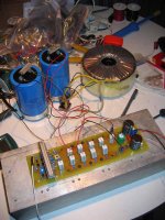
I have one of the modules fired up and it rocks! Its first thing that came out of it was the Dennis Hopper bit on Gorillaz Demon Days. But that was what was inside the Portable CD player.
Board B is next, then the case and on to some real listening. Observations right now; it is very loud and has a tremendous head room. The transformer and large heat sink are room temperature. I might put on a dummy load and blast it to hell. I have 4pcs of 5ohm 100watt wirewounds.
Now what is the set up...Quatro, get on your computer🙂
Shawn.
Shawn,
Excellent. I am sure you can hardly wait for the case to return back to put it all together.
Quick few quick questions:
1) How cool, warm, hot is the onboard heatsink for the drivers?
2) Many have made reference to how "loud" quasi's amp is. I understand what excellent dynamics means, but I have no clue what "loud" means in what I assume is the qualitive, or perhaps it is an objective qualitive, word.
3) What did you set your bias to?
4) What is the V rail while your amp is idle at the PCB MOSFETs?
Regards,
John L. Males
Willowdale, Ontario
Canada
21 June 2006 01:37
[Q
But more so than all this is the sound. I hooked up a little studio monitor design I've ben working on since the 80's. I think I'm one step away from finallizing the design, well, I couldn't help myself, I hooked one of the monitors up to Quasi and voila, brilliance! The vifa tweeter was amazing and the stage was large but I need to finish the full amp before getting carried away. I think the Quasi could be like a giant Mark and Levinson with real balls. Or a Bryston without the uneccessary kindness. Make any sense?
I am a little disappointed by the previous builders of this amp on this thread. I think it is very likely each of them has used sub-par components to build, each at different points in the design. Because they should all come back screaming about the open sound stage and ENDLESS headroom. I made no such sacrifices and still I’m waiting for some “high-end” caps to use on the input.(early next week I’ll have them) so my sound is only going to get better.
More rigid guidelines may need to be given to builders to realize what the Quasi has intended.
No more about sound until it is in the case and running stereo. Back to soldering. John, is your solder iron plugged in or is it still in the blister pack? I'm bad! You can beat me up if you want to.
What's the set up?
Shawn.
Warm, very warm but you can touch it. I'd guess the entire sink may have a couple watts of dissipation on it but I'm guessing.originally posted by keypunch
1) How cool, warm, hot is the onboard heat sink for the drivers?
I have a sound level pressure meter and a frequency generator/counter to go with it to measure STC sound levels, I use this at work to measure my studio designs. I guess I could set it up at home but what is the point? I and my speakers could only stand so much and it would be a high dB but the amp would be taking a nap.This amp will deliver, more so it will deliver into a difficult and low resistance load=POWER...1KVA of transformer and and 20 IRFP450s has got to do something. The head room is endless as I do not have a speaker set up or a room large enough to unfurl this freaky beast. It needs a concert hall or a mad scientist Hi-Fi nutt with some crazy 1 ohm load speakers. Really I need to take it to a concert hall to unwind it into an array of speakers. It is just to much power...That is the reason why I chose it! I wanted the excess.2) Many have made reference to how "loud" quasi's amp is. I understand what excellent dynamics means, but I have no clue what "loud" means in what I assume is the qualitive, or perhaps it is an objective qualitive, word./B]
I did not set it, I don't know how to set it and I can't find it in the thread for the 10 mosfet PCB? I'm affraid to set up some nasty tests 'cause it may not be ready yet.3) What did you set your bias to?/B]
I'm very dissipointed by the rail voltages as it meaures +/-56.2VDC. I was hoping for 62VDC as I estimated. It is not a great concern because the damn thing works so great but I may open my eyes to some 1KVA 60-0-60 toroids cause I think this circuit really needs it...to be be pushed that is. I would like to drive the ten mosfet board to it limits and then back it off a little and set up shop there...Who said that?...Tubelab (http://www.diyaudio.com/forums/member.php?s=&action=getinfo&userid=48762 ) . And well said as it is the way I think too.4) What is the V rail while your amp is idle at the PCB MOSFETs?[ B]
But more so than all this is the sound. I hooked up a little studio monitor design I've ben working on since the 80's. I think I'm one step away from finallizing the design, well, I couldn't help myself, I hooked one of the monitors up to Quasi and voila, brilliance! The vifa tweeter was amazing and the stage was large but I need to finish the full amp before getting carried away. I think the Quasi could be like a giant Mark and Levinson with real balls. Or a Bryston without the uneccessary kindness. Make any sense?
I am a little disappointed by the previous builders of this amp on this thread. I think it is very likely each of them has used sub-par components to build, each at different points in the design. Because they should all come back screaming about the open sound stage and ENDLESS headroom. I made no such sacrifices and still I’m waiting for some “high-end” caps to use on the input.(early next week I’ll have them) so my sound is only going to get better.
More rigid guidelines may need to be given to builders to realize what the Quasi has intended.
No more about sound until it is in the case and running stereo. Back to soldering. John, is your solder iron plugged in or is it still in the blister pack? I'm bad! You can beat me up if you want to.
What's the set up?
Shawn.
Hi Tom,
I just got lazy, could you remind me what transformer spec you are using to generate your +-56V2?
This is @ quiescent and no output to your load.
What Vac does your transformer deliver into open circuit?
I just got lazy, could you remind me what transformer spec you are using to generate your +-56V2?
This is @ quiescent and no output to your load.
What Vac does your transformer deliver into open circuit?
I did not set it, I don't know how to set it and I can't find it in the thread for the 10 mosfet PCB?
Lucky stiff !
www.diyaudio.com/forums/showthread.php?postid=799657#post799657
Faulty connections!
I was going to hit the hay but I saw your post...
The (- )screw terminal on the caps is a little corroded and I did not tighten them enough, so as it turns out I now have +/- 60.2 VDC from 44-0-44 AC. The bridge drops 1.1V on each junction. Part # is GBPC5010. All is good.
Sorry,
Shawn.
T, you rock, thanks.
AndrewT said:Hi Tom,
I just got lazy, could you remind me what transformer spec you are using to generate your +-56V2?
This is @ quiescent and no output to your load.
What Vac does your transformer deliver into open circuit?
I was going to hit the hay but I saw your post...
The (- )screw terminal on the caps is a little corroded and I did not tighten them enough, so as it turns out I now have +/- 60.2 VDC from 44-0-44 AC. The bridge drops 1.1V on each junction. Part # is GBPC5010. All is good.
Sorry,
Shawn.
T, you rock, thanks.
Hi,
Iq=150mA for 10 FETs seems quite low.
Most FET output stages seem to benefit from much higher Iq.
I run 75mA per pair (Sugden recommendaton), Borbely recommends 500mA minimum.
Has Quasi designed this to be set up with a deliberately low Iq?
Iq=150mA for 10 FETs seems quite low.
Most FET output stages seem to benefit from much higher Iq.
I run 75mA per pair (Sugden recommendaton), Borbely recommends 500mA minimum.
Has Quasi designed this to be set up with a deliberately low Iq?
jacco vermeulen said:
Excellent Jacco! Where do I measure the "150mA" from? I have no reference here. Looks like you know? Lay it on me or I won't sleep tonight! I don't want links, I want solder! 🙂
Shawn.
Top ten
Yee just put Quasi in the Top Ten for Replies! Congrats and when the Quatro returns he'll hit 200 posts on this thread! Good times! I really need sleep now, are you people just heading to work? I've got 2:30AM on the clock!
Yee just put Quasi in the Top Ten for Replies! Congrats and when the Quatro returns he'll hit 200 posts on this thread! Good times! I really need sleep now, are you people just heading to work? I've got 2:30AM on the clock!
Hi Tom,
go to bed and earn your keep then think about the next bit.
Caught your 60V2 reply.
Still seems low.
44Vac *root 2 *1.05 (regulation) =65v3
Your 1v1 across each diode seems enormous, or is that across a pair of diodes (Vf=550mV is low)?
What is you mains input voltage compared to the transformer rating? 110Vac into a 120Vac transformer will lose a lot of voltage.
If 44Vac is correct then you should have about 46V2 ac on open circuit, but dependant on regulation and mains voltage.
BTW. "Coppaslip" or "Vaseline" are good for electrical connections, but be very sparing with Coppaslip, it conducts!
My IQ varies but when the shrink Doctor tested it, it was 140 😉AndrewT said:Hi,
Iq=150mA for 10 FETs seems quite low.
Most FET output stages seem to benefit from much higher Iq.
I run 75mA per pair (Sugden recommendaton), Borbely recommends 500mA minimum.
Has Quasi designed this to be set up with a deliberately low Iq?
I have not turned a pot as I don't know for certain where and what the measurments should be. As it is the thing is sleeping and there is no way I can draw a large current from it without destroying speakers. I could go pick one of those 18" subs and give it a whirl, and I'd like that very much but ...soon...time.
Shawn.
AndrewT said:44Vac *root 2 *1.05 (regulation) =65v3
Your 1v1 across each diode seems enormous, or is that across a pair of diodes
It is a bridge in "a Box" rectifier. High current, 50Amps! Too much perhaps. see the spec sheet for these things: 1.1VDC drop per junction is the way it goes. I may say go away with the bridge if I find a better one or a more suitable one.
Thanks a bunch,
Shawn.
P.S. as long as yer hitting the thread and I'm awake, then I will reply. Work tomorrow is up to me, I'm in charge. Tonight I drink beer and build amps!
AC Line Voltage
I've got a solid 118VAC through the Duplex Outlet supplying the AC mains of this XFMR. 44-0-44 VAC comming out measured on Digital VOM.
Thanks,
Shawn.
I've got a solid 118VAC through the Duplex Outlet supplying the AC mains of this XFMR. 44-0-44 VAC comming out measured on Digital VOM.
Thanks,
Shawn.
hi tom,
sorry to butt in, how about 6 pairs of irfp450 ?
does that makes sense if i'm in for serious power and enough juice from ps ?
are the mje's capable ?
thanks
sorry to butt in, how about 6 pairs of irfp450 ?
does that makes sense if i'm in for serious power and enough juice from ps ?
are the mje's capable ?
thanks
VDC no Load
I removed the 2700ohm! 10Watt resistors bypassing each of the main caps and I read +/- 61.1VDC going into the amp module. I'm using these R's to discharge the main caps rapidly between handling. Perhaps not a good idea?
Shawn.
I removed the 2700ohm! 10Watt resistors bypassing each of the main caps and I read +/- 61.1VDC going into the amp module. I'm using these R's to discharge the main caps rapidly between handling. Perhaps not a good idea?
Shawn.
TomWaits said:Where do I measure the "150mA" from?
The brown trimpot on your board sets the bias.
There's no guarantee that it is set in max resistance position or minimum resistance when you buy it or install it in your board, unless you checked.
With the 470, 47 Ohm, and 200 Ohm trimpot resistor values of the Vgs multiplier you'll have 1.74 Volts or 9.15 Volts across the drivers, in the max or minimal position of the trimpot.
If it's 1.74 volts there's no problem.
If it's 9.15 the output stage would be in the max bias setting.
The 30 mA is for each output device. Measure with a DMM in Vdc setting across a 0.47 resistor, 30 mA corresponds with 14 millivolts.
Other option would be to remove one of the fuses, place a 5 or 10 Ohm resistor across the fuseholder and adjust the bias for 1.5 volt drop across the 10 Ohm resistor or 0.75 volts across 5 Ohms.
(for both 5 or 10 Ohm values a 1/4 watt resistor will do)
My Rails are:
My rails voltage is +/- 61VDC. My paralllel output resistors are 0.39ohms each. Does that change yer math?
Shawn.
jacco vermeulen said:
The brown trimpot on your board sets the bias.
There's no guarantee that it is set in max resistance position or minimum resistance when you buy it or install it in your board, unless you checked.
With the 470, 47 Ohm, and 200 Ohm trimpot resistor values of the Vbe multiplier you'll have 1.74 Volts or 9.15 Volts across the drivers, in the max or minimal position of the trimpot.
If it's 1.74 volts there's no problem.
If it's 9.15 the output stage would be in the max bias setting.
The 30 mA is for each output device. Measure with a DMM in Vdc setting across a 0.47 resistor, 30 mA corresponds with 14 millivolts.
My rails voltage is +/- 61VDC. My paralllel output resistors are 0.39ohms each. Does that change yer math?
Shawn.
30 mA times 0.39 Ohms is 11.7 millivolts voltagedrop across the resistor.
For the resistor in the fuseholder method it makes no difference.
For designs with fuses on the rails i've found it the easiest way to properly set the bias.(and safest)
You can only measure across 1 of those resistors with a quasi-complementary setup, because there's a Mosfet between 2 of the white cubes. With fully complementary designs you can measure the voltage drop across 2 resistors, which is more accurate.
(i used to have an IQ, but i lost the Q, it has been much more quiet since)
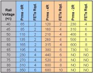
Talk to Quasi. He posted this table but I'm certain it is not written it stone. You will have issues with the current carrying capability of the traces on your circuit board etc. Many issues evolve fro high current applications. I'll step aside and the wizzards will advise. Does this mean you will out beat me on the Quasi amp! Jeeze, I can't stand for it, already I forsee bridged versions in mono blocks delivering over 1KW per channel but that is just me...rolandong said:hi tom,
sorry to butt in, how about 6 pairs of irfp450 ?
does that makes sense if i'm in for serious power and enough juice from ps ?
are the mje's capable ?
thanks
Shawn.
Look to Quasi's table for initial guide. Yes I believe this amp can do more but the PCB and drive circuity would need adjustment. Yes is the answer, I know it can deliver more.
Attachments
- Home
- Amplifiers
- Solid State
- Power amp under development