Hi Shawn,
As quasi once said of me, I am a very "logical" thinking person. The spreadsheets were done over a year ago. So I just use then to do the what if's and add any "interesting" output devices to see how stack to my shortlist of output devices. Frankly adding more devices has not happened for about 9 months.
My gosh I love your heatsink *drooling*, I wish I could find such lovely heatsinks. Your modules look clean and well made both the compoents and PCB build. Excellent work Shawn. What T8 device did you choose?
Enjoy the hockey game.
Regards,
John L. Males
Willowdale, Ontario
Canada
19 June 2006 22:13
Hi,
I understand rail losses to be the drop in voltage from and including the transformer, through the rectifier and smoothing caps to the PCB supply rails feeding the output devices. On that basis the number of output devices cannot have a significant effect on the rail losses if the load stays the same and the input/output voltage stays the same.
If you take the alternative, with rail losses meaning the voltage loss from the PCB supply through the output devices, emitter/source resistors, output cabling and network to the speaker terminals then this version of rail losses is inversely proportional to the number of devices. Again I am assumming that to allow comparison the load and input/output voltages remain the same.
Both definitions result in either, better rail loss or no change as the number of output devices are increased.
There could be a third alternative. If one were to assemble a single pair output stage with no emitter/source resistors and then compare it to a multiple parallel pair output stage with large value emitter resistors (1r0 or more) and for each additional pair to increase the emitter resistor values, i.e. 3pr 1r5, 4pair 2r0, to maintain the same effective parallel resistance across the resistors, then it is possible that the losses using the second definition from above could be worse in multiple pairs, particularly if one were to adjust the emitter/source resistors upwards to ensure that the losses measured worse.
Over to you Keypunch.
what is your definition of rail losses?the more output devices there are the larger the rail losses. One reason some like to build using only one pair of output devices, as well as no need for emitter resistors using one pair, is to keep rail losses to bare minimum. There are pros and cons sonic quality of using just one output device pair. Aside from the more parallel pairs adding to rail losses, the required emitter resistors add to the losses, in combination with bridge, filter capacitor and other PSU elements
I understand rail losses to be the drop in voltage from and including the transformer, through the rectifier and smoothing caps to the PCB supply rails feeding the output devices. On that basis the number of output devices cannot have a significant effect on the rail losses if the load stays the same and the input/output voltage stays the same.
If you take the alternative, with rail losses meaning the voltage loss from the PCB supply through the output devices, emitter/source resistors, output cabling and network to the speaker terminals then this version of rail losses is inversely proportional to the number of devices. Again I am assumming that to allow comparison the load and input/output voltages remain the same.
Both definitions result in either, better rail loss or no change as the number of output devices are increased.
There could be a third alternative. If one were to assemble a single pair output stage with no emitter/source resistors and then compare it to a multiple parallel pair output stage with large value emitter resistors (1r0 or more) and for each additional pair to increase the emitter resistor values, i.e. 3pr 1r5, 4pair 2r0, to maintain the same effective parallel resistance across the resistors, then it is possible that the losses using the second definition from above could be worse in multiple pairs, particularly if one were to adjust the emitter/source resistors upwards to ensure that the losses measured worse.
Over to you Keypunch.
Thanks AndrewT, that's a good detailed explanation.
When I posted the table of indicative powers I assumed a very large power supply with good regulation i.e. around 5% plus the FET voltage drop (including Vgs). This means that the table is a bit optimistic and constructors are unlikely (unless they way over-engineer) to achieve the powers indicated in RMS terms. In dynamic terms though it should be pretty close and this is more important when listening to music (IMO). In any case if you are aiming for 200 watts and you only achieve 180 I doubt you will hear it.
My my Shawn that is a big main heatsink. Concerning the other one (the one that is supported by the transistors only!) how does it feel?
Anyway I go to some length to make sure the 10 FET board can be printed on an A4 page, and what do I discover? .....a mezzanine DC detect board?
Seriously your construction thus far looks good, let us know when you fire it up.
Cheers
Andrew,
I am not as adept at the theory of rail loss as you or quasi are. That said, I cannot offer you a "definition" of rail loss with respect to point of reference, i.e. PSU to PCB, or PCB to MOSFET, or MOSFET to load, or PCB to load. I know a lower impediance typically causes most PSU to sag, i.e. show higher rail loss and I suspect in that case it has to do with the speaker load. What I stated is what I have read about in many different places her
e and other places by many different authors. That said, I can tell you the only reference I know has been mentioned is that MOSFETs have higher rail loss than do BiPolar output device stages used in similar designs. There may be exceptions to that rule and if so, I have not yet run across such reading yet.
As to the emitter resistors adding to the rail loss, I was never assuming more that usual 0R22 - 0R33 most designs use, not even quasi's preference for 0R47 emitter resistors. Again my comment about rail losses due to the emitter resisters (most agree should be used when there are parallel output devices) was based on many other persons comments from various sources that suggested emitter resisters added in a major way to rail losses for the commonly used values 0R22 - 0R33.
I do not know enough about the specific theory related to rail losses. It does seem almost universial that BiPolar output devices have less rail loss than a MOSFET output device stage of same general amp design. If this is not true please correct me.
I do know that at best one can only estimate a rather rough ballpark of rail losses to determine final output power.
As I indicated in my initial comments I was open to comments or corrections to what I uderstood about rail losses thus far in my knowledge and reading the past 18 months. I am humble that way, and I am quite fine being corrected of what can be common myths many people may feel is fact and I have so concluded, perhaps in error, as fact.
As to quasi's chart. Yes it was very ideal in terms of design/low losses, which I knew. In my dimensioning approach to the output devices I error on the ideal side to determine number and ratings of output devices to use. Then on the theory side I run some numbers as first estimate and will compare those to the actual once I have a couple modules under my belt. I will likely do a few comparisons right off the bat. First will be using the common PSU design of one bridge and filter cap bank to two modules, then dual bridge and caps on each side of bridge feedign two modules, then two bridges with caps for each module, and then finially a variation of the TNT PSU design that has a thread on DIY Audio, but I do not have the link to the thread handy. I need to find that thread again.
I agree with quasi the difference between 180W RMS or 200W RMS is not that big a deal, especially in db terms. With the exception of a woofer/subwoofer channel that likely would be at ease with a 200W amp, I really do not see much of a need for over 60W RMS for 8 ohms, 120W for 4 ohms amps. This is more so when doing an active crossover setup, even if it is just bi-amping. If tri-amping, I personally feel the tweeter amps do not need to be more than 15-20W RMS. For my conservative design approach I tend to design to RMS rather than Peak to Peak for my Peak to Peak target handling. My reason is organ music can be more demanding of an amp over time of passage than many other forms of music. I based this on actual V RMS meter monitoring trials. I have also found that it seems that one needs about 12-15 db of headroom in and about the low to mid playing level one normally plays an amp at, for home use. For PA or DJ applications the dimensioning is a whole different set of criteria.
Someone in another thread has indicated that an amp should handle 1/2 the full gain design using P-P square or sine wave to constantly ensure an amp input and output stage and thermal design is covered off. One commerical amp I have that I tested this on bears truth to this approach. I take that criteria as an excellent test to validate a design and DIY'er dimensioning of output devices/stage with PSU to prove a execution as stable.
I hope between my initial comments, those of Andrew, and quasi that followed and my follow up comments that at least the "definition" is a bit clearer, i.e. I really had no definition nor reference point from my reading to date as I researched how to dimension PSU, output devices vs Supply vs actual rail +-V.
I actually hope to have a bit of time today to do some more shopping to find some of the parts I still need to even build a initial pair of modules. I still need to find more of the MJE's, and good cap for the feedback to ground cap.
I also have had a excellent electronic book for a number of years, and I have been reading some of the theory on RC and time constants, and such. I may change the feedback loop to ground RC from a 67% to 90%+ time constant. I am looking at different C values on input filter to see if I wish to change the -3 db rolloff point a tad higher. I may need to modify the PCB to accomodate a a couple caps physically larger than the current PCB can handle. That will take lots of time and patience. Sometime I also need to update the project web site I started last winter with lots of find notes, faq, etc this thread has regarding quasi's amp in hope of reducing some of the repeating common questions and makeing it easy to find some of the less asked questions that are none the less very informative.
Regards
John L. Males
Willowdale, Ontario
Canada
20 June 2006 06:18
I
Just curious....
_
Just curious dear readers, quite a few 6 FET versions have been succesfully built, but I am not aware of any completed 10 FET versions. So is Shawn's amp the first 10 FET version about to be fired up, or have others built it?
I am very interested in any that may have been built and any feedback (and pics) offered.
Cheers
keypunch said:an excellent electronic book
Care to give the title ?
(Quasi, whip Guuseroo for the Croatia/Hrvatska thingy)
If Australia 3 v Japan 1 and Croatia 0 v Japan 0;
Then Australia n - Croatia 1 = Croatia - Japan
Therefore n-1 = 0
Therefore Australia 1 v Croatia 0
...simple no?
Then Australia n - Croatia 1 = Croatia - Japan
Therefore n-1 = 0
Therefore Australia 1 v Croatia 0
...simple no?
Hi,
I do not agree with this
The main difference between the various drivers is the sensitivity. In general tweeters tend to be more sensitive, resulting in the need for less drive voltage. It is this that leads to the differing power requirements.
I do not agree with this
I believe that the voltage requirement for a tweeter is very similar to that for the other speakers in the active setup when all the speakers are of equal sensitivity.With the exception of a woofer/subwoofer channel that likely would be at ease with a 200W amp, I really do not see much of a need for over 60W RMS for 8 ohms, 120W for 4 ohms amps. This is more so when doing an active crossover setup, even if it is just bi-amping. If tri-amping, I personally feel the tweeter amps do not need to be more than 15-20W RMS.
The main difference between the various drivers is the sensitivity. In general tweeters tend to be more sensitive, resulting in the need for less drive voltage. It is this that leads to the differing power requirements.
Re: Just curious....
I like the thought of that, is it a race to the finish, do I get a prize…oh yeah, I get a nice amp.
Shawn.
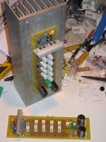
The driver heat sink is good and very light but I’m worried long term vibration and mechanical shock would jeopardize the solder points so I have reconsidered and mounting brackets are a must.quasi said:My my Shawn that is a big main heatsink. Concerning the other one (the one that is supported by the transistors only!) how does it feel?
And it breaks your heart🙂 There is a few reasons and luck too. I decided when reading the beginning of the thread to build the Quasi amp, then further in reading the 10fet amp came up but I already bought a few parts ie PCB boards. I use presensitized PCBs and the 12 inch boards cost a small fortune$$. The aluminum extrusions will be stacked side by side with the fins vertical for max convection. Two extrusions wide only measures 10-1/4 inches, that’s lucky.quasi said:Anyway I go to some length to make sure the 10 FET board can be printed on an A4 page, and what do I discover? .....a mezzanine DC detect board?[/B]
Thank you but I have a few questions first in a post to follow…quasi said:Seriously your construction thus far looks good, let us know when you fire it up. Cheers [/B]
I purchased 4 or 5 of those and it measures 3-1/2” by 5-1/16” by 14” long. The PCBs will be mounted perpendicular to the direction on the fins and the image is just a test set up. Also, in the same purchase there is a bunch of heat sinks of the same extrusion but the length is shorter at 9-1/4 inches long. I have 4 of the smaller ones.bigpanda said:Hi Shawn,
Just what size of heatsink are we looking at ?
quasi said:. So is Shawn's amp the first 10 FET version about to be fired up, or have others built it? Cheers
I like the thought of that, is it a race to the finish, do I get a prize…oh yeah, I get a nice amp.
Shawn.
Initial power up
Set up and test:
Open potentiometers to highest ohm
Replace fuses with 100ohm resistors?
Then what?
Shawn.
P.S. I have a variac, scope and two digital VOMs.
Set up and test:
Open potentiometers to highest ohm
Replace fuses with 100ohm resistors?
Then what?
Shawn.
P.S. I have a variac, scope and two digital VOMs.
Hi Tom,
plug in your series mains light bulb, it''ll protect the Variac if your amp has a short or serious overload.
I assume you have built one.
It consists of plug top, bulbholder and socket outlet. It can be used for first start up of any mains project.
plug in your series mains light bulb, it''ll protect the Variac if your amp has a short or serious overload.
I assume you have built one.
It consists of plug top, bulbholder and socket outlet. It can be used for first start up of any mains project.
IRFP450 isolation on tab
The data sheet for the International Rectifier IRFP450 says," ...the TO-247 is similar but superior to the earlier TO-218 package because of its isolated mounting hole."
I have seen in various pictures people mounting these FET's with insulated washers? Are these people using a different FET? I tested the conductance from the three leads to the steel portion on the backs of these HEXFETs and there is none.
Can I mount just using grease and a bolt? It all sounds right to me and I would get much better heat dissipation.
Cheers,
Shawn.
Hi Shawn,
that's about the mounting hole. The screwhead (there it is again 😀) rests on top of the plastic device...
that's about the mounting hole. The screwhead (there it is again 😀) rests on top of the plastic device...
Screwsheads and IRPF450s
Is it safe to mount without insulating washer?
Shawn.
(there it is again) You rock.
P.S. I remember the slang of that expression from the classic DeNiro flick Taxi Driver and of later impression as sampled by The Clash in the lyric from Red Angel Dragnet. Everytime I see it or hear it, trigger...I'm weird.
The top and the shaft of the through mounting hole have no metal near them. On the back, mounting side, there is a piece of bare metal but it does not make electrical contact with any of the three leads on the device.sek said:Hi Shawn,
that's about the mounting hole. The screwhead (there it is again 😀) rests on top of the plastic device...
Is it safe to mount without insulating washer?
Shawn.
(there it is again) You rock.
P.S. I remember the slang of that expression from the classic DeNiro flick Taxi Driver and of later impression as sampled by The Clash in the lyric from Red Angel Dragnet. Everytime I see it or hear it, trigger...I'm weird.
Re: IRFP450 isolation on tab
Shawn,
You had my curiousity sparked from your reading and observations of the IRFP450. I took out some IRFP450s and checked them. Sure enough the middle lead, drain, is same as the metal back electrically. In other words the drain lead and metal back are same.
I think the reference the IRFP450 datasheet makes, that you quoted, at start of data sheet is strickly about the mounting hole, which is in fact isolated. The older IRF data sheets, including IRFP450, IRFP240 do not list the case and pinout information on the datasheet, but refer one to a different page that is of course not part of the data sheet.
The IRFP450 information is found at:
http://ec.irf.com/v6/en/US/adirect/ir?cmd=catProductDetailFrame&productID=IRFP450:
On that page is a link to the package type "TO-247AC" that leads you to:
http://www.irf.com/package/pkhexfet.html
On that page you will find "TO-247AC", "Package Outline"
http://www.irf.com/package/hexfet/to247.pdf
Here you will note that "2" and "4" are both drain, "2" being the pin, an "4" being the "THERMAL PAD" of "VIEW A-A".
This means that you still have to insulate the IRFP450's from the heatsink, notwithstanding the mounting hole is in fact insulated.
I hope this clarifies why you still need to insulate electrically, but thermally couple the IRPF450 to the heatsink or for that matter any TO-247(AC) case stype device.
Regards,
John L. Males
Willowdale, Ontario
Canada
20 June 2006 18:18
Re: Re: IRFP450 isolation on tab
I will be using the external T8 in the actual power amp but for testing I am in the hole.
 !!! As you were. Thanks John.
Again whats the set up procedure and measurements to set the two pots?
Shawn.
Canadian players win but Canadian teams can not and what is up with the Losers, I mean Leafs? Ha Ha its all over.the drooling keypunch said:What T8 device did you choose? Enjoy the hockey game
I will be using the external T8 in the actual power amp but for testing I am in the hole.
I appologise everybody, the back tab shares the drain. I did the measurements last nightOriginally posted by keypunch This means that you still have to insulate the IRFP450's from the heatsink...[/B]
!!! As you were. Thanks John.Again whats the set up procedure and measurements to set the two pots?
Shawn.
jacco vermeulen said:
Care to give the title ?
(Quasi, whip Guuseroo for the Croatia/Hrvatska thingy)
Hi Jacco,
Here is the information for the book:
Thomas L. Floyd
ELECTRONICS FUNDAMENTALS: CURCUITS, DEVICES AND APPLICATIONS
Merrill Publishing Company
A Bell & Howell Information Company
Columbus Toronto London Melbourne
Published by
Merrill Publishing Company
A Bell & Howell Information Company
Columbus, Ohio 43216
Copyright 1987
Library of Congress Catalog Number: 86-61567
International Standard Book Number: 0-675-20714-2
Published in the United States of America
4 5 6 7 8 9-91 90 89
Regards,
John L. Males
Willowdale, Ontario
Canada
20 June 2006 19:46
20 June 2006 20:13 Removed stray quote jlm
Hi Shawn,
I was aware you would use an "external" T8, and it would be a TO-126 device. I was curious what you were going to use, as in a BD139, etc?
Have you fired up either of the modules yet? Even tried to play music through after the initial Vbe bias setup?
Regards,
John L. Males
Willowdale, Ontario
Canada
20 June 2006 20:12
- Home
- Amplifiers
- Solid State
- Power amp under development