Hi Sakis,
Nice to hear from you. I don't think that this amp is really suitable for a lower voltage - highly biased application. The output FETs drop around 6-7 volts so this will make it quite inefficient for lower rails. At higher voltages this is less of an issue (in percentage terms).
The other FET amp; Another quasi-complementary design would be better as it drops very little voltage. A few component (resistors mostly) changes would have to be made.
Anyway I have started a new project; A high power complementary design to refit an empty Proton D1200 chassis a friend of mine gave me. I hope to post some details soon.
Some photo's of my very slow progress below.
Cheers
Thanks Quasi
the question is not related to efficiency or delivered power
the question is will it sound better ?
Thanks Quasi
the question is not related to efficiency or delivered power
the question is will it sound better ?
The specs should improve but as for the sound the only way to tell is to build it. Existing modules can be modified as a quick check. Let me know if you going to to that and we can talk about some component changes.
Cheers
Q
Quasi, looking great !
Thanks Jan
Link to the build. https://www.diyaudio.com/forums/sol...proton-d1200-restoration.html?highlight=D1200.
Cheers
Q
Hi!
You can check my project. I used EasyEDA to design PCB and then order it from China. It works great!
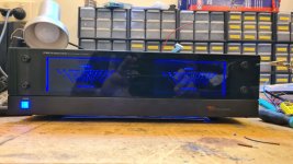
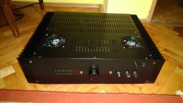
Amplifier ACTRK600 -
EasyEDA
You can check my project. I used EasyEDA to design PCB and then order it from China. It works great!
Amplifier ACTRK600 -
EasyEDA
Hi cmircea86,
Very impressive build - well done. Good YouTube videos too.
Looking at your power measurement results your amp will actually deliver higher dynamic (short term) power, closer to 290w into 8 and 520 into 4. Your output stage is bullet proof too, you can run higher rails if you want.
Nice job.
Cheers
Q
Thanks a lot for your appreciation. Indeed, the rail could be higher, but for now I use it with the trafo I have that is +/-76V plus 10V for command stage. Maybe in the future I will build a better transformer. For now I use two modules with a pair of t.box 252 eco mk2 (500W - 4 ohm) and it drives them very well.
Attachments


Last edited:
Quasi, If I don't need 200W output power, can I use only one pair of IRF840 for NMOS 200 amp? Would it be 100W output?
Quasi, If I don't need 200W output power, can I use only one pair of IRF840 for NMOS 200 amp? Would it be 100W output?
Hi Rankot,
If you require 100w into 8 ohms then you could run 48v to 50v rails with one pair of IRF840. You must ensure though that it is never connected to a 4 ohm load. Also this amp is strictly for HiFi; use as an instrument or a PA amp will kill it.
If you require 100w into 4 ohms then you will need to drop the supply rails to 36v.
Cheers
Q
Thanks! I actually need it for a bass amplifier. 🙁Hi Rankot,
If you require 100w into 8 ohms then you could run 48v to 50v rails with one pair of IRF840. You must ensure though that it is never connected to a 4 ohm load. Also this amp is strictly for HiFi; use as an instrument or a PA amp will kill it.
If you require 100w into 4 ohms then you will need to drop the supply rails to 36v.
Cheers
Q
Can I modify it somehow so it can be used like that? If not, is there any similar amp which can be used for such a purpose?
Hi Rankot,
If your bass speaker box has one 8 ohm speaker then I would build the NMOS200 with 4 IRF840 or similar and use 50v rails. If the speaker impedance is 4 ohms then drop the supply rails to 36v. Have a look also at Apex's amp https://www.diyaudio.com/community/threads/150w-mosfet-amplifier-with-irfp250x2.163159/ as well.
If budget permits you could build the Nmos350 for a bullet proof solution and run that on 50-60 volt rails.
Cheers
Q
OK, I would do that. I already have ±40V PS, so I will use that one with NMOS200. Is it OK to use only one pair of IRF840 with both 4 and 8 Ohm impedance speakers using that power supply? I don't need full 100W power, just enough to play in my room and be safe with both speakers and to know that I will not damage them or amp.Hi Rankot,
If your bass speaker box has one 8 ohm speaker then I would build the NMOS200 with 4 IRF840 or similar and use 50v rails. If the speaker impedance is 4 ohms then drop the supply rails to 36v. Have a look also at Apex's amp https://www.diyaudio.com/community/threads/150w-mosfet-amplifier-with-irfp250x2.163159/ as well.
If budget permits you could build the Nmos350 for a bullet proof solution and run that on 50-60 volt rails.
Cheers
Q
Why don't you recommend using this amp as an instrument amplifier?
Hi Rankot
This amp is a little lightweight for your application. Musical instrument applications are more power demanding than general music, particularly keyboards and guitars. Hitting a sustained note on a bass guitar will have a higher current delivery duty cycle than average music. I would still use 4 IRF840's to be safe - not very expensive and the pcb is ready.
Cheers
Q
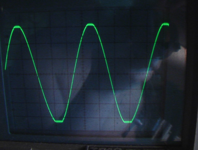
I've simulated this (still waiting for PCB to arrive) and I get much better result with 1N4007 than LED on this. What was your final conclusion? The most recent schematic I found still has 100 Ohm resistor there.NMOS200 Scope pictures
My NMOS200 with R21 exchanged with Yellow LED (1.9V)
Much better clipping. Near symetrical
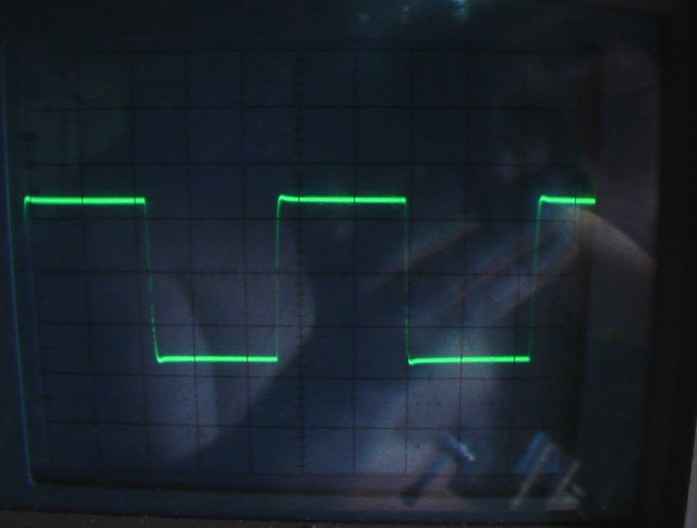
Same module and the 10khz Squarewave. Also less overshoot. Original signal from functiongenerator not shown here but was almost perfect (slightly undercompensated)
Nearly no sign of crossover.
Hi Rankot
The 100 Ohm resistor is part of the original design. Some constructors have replaced it with either a string of 3 diodes or a yellow/green LED. The diodes give better peformance although it would not be noticeable in a bass guitar amp. I'm sure the single diode provides an improvement as well. Up to you.
Cheers
Q
Good day Quasi,
I joined DIYAudio some ten years back and built your NMOS500 amplifier. IRFP460 output Mosfets running 90 VDC rails.
It has served me and my parties very well, always get compliments on sound quality and power, until recently where I left the music mixing up to some teenagers and I think they overdrove the amp.
The faults I have come accross are R2 (10e resister) went OC and it seemed one of the 10 mosfets gate shorted, on the negative rail side.
The other MOSFETS seem OK.
Before I strip out all the active components and test each one perhaps you could guide me in terms of possible initial stage trasnsistors that may need replacing, or why there would be an excessive current flow through this ground resistor?
Furthermore, after reviewing this thread again i have seen some MKII upgrades like replacing R21 with LED/diodes is this worth looking into as an upgrade.
I also found the "power selection guide" recently where rails above 80 VDC require the gain resistor to be increased from 33k to 39k, is this advisable given I am runing 90 VDC rails?
Your expert advise is appreciated.
Thank you
- Home
- Amplifiers
- Solid State
- Power amp under development