Hi Nmos,
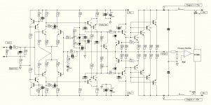
Great idea. So for complementary BJT's it looks good. I just Simmed the schematic I'm working on for output rails between 10 to 80v - no problems. I hope this picture shows what you mean. For ACTRK might be a bit trickier. For complementary MOS should be no problem. Lets talk more.
Great idea. So for complementary BJT's it looks good. I just Simmed the schematic I'm working on for output rails between 10 to 80v - no problems. I hope this picture shows what you mean. For ACTRK might be a bit trickier. For complementary MOS should be no problem. Lets talk more.
Attachments
Hi quasi,
Those are my favorite output transistors. Matching is very tight, even between polarities.
That's quite the beast you're designing and it should sound very good. With those supply voltages I can see why you are concerned about Vas heating. You'd be using at least parts with a TO-126 package I would think. They could then take advantage of a small heat sink if it was really needed.
-Chris
Hi Chris
I was actually looking around for some higher power output transistors but a local supplier ran these out on special. I actually had never heard of them before and was super impressed by the specs. I paid about $1.70 AUS ($1.50 CAN) a piece so I bought a couple of rails of each type. I hope 4 per side is enough.
For T9 & T10 I'm thinking a quality low power TO126 (let me know what your favourites are) as they only pass about 1.5mA and mounting with thermal coupling is easier. Not decided though on T11 & T12 and I don't really want to go the MJE340/350 path. But as you say this stage will get hot so it will be tricky.
I'm hoping this is the best power amp I've made so fingers crossed.
Cheers
Q
Last edited:
Hi quasi,
Had those outputs gone on special near me, I would have bought at least a rail of each! I did get samples and they tested very, very well. Then I bought a few before they were discontinued (by surprise). These outputs would go into the highest quality designs you had. They are lovely parts.
Your DC supply voltages are very high for the voltage amp stage and that will force your hand as to what parts you end up using. This may well force you into a TO-220 package for T11 and T12. You may be stick with MJE340/MJE350 unless you can find some good 200V parts. It's been a couple years for me, so I'm not certain about part numbers. Sorry I couldn't be of more help.
This has the potential to be an excellent power amplifier. I can hardly wait until you complete it for your impressions.
Best, Chris
-Chris
Hi folks
I might start a thread on this amp later, but a question if I may.
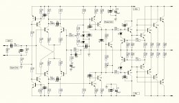
I've been struggling with the choice of the second stage transistors - it is difficult to find one with good linearity that can take the heat. So I thought about paralleling 2 x 2SA1381 / 2SC3503 instead of 1 x MJE350 / MJE340.
What do you think? Is this ok, or is paralleling here problematic.
I might start a thread on this amp later, but a question if I may.
I've been struggling with the choice of the second stage transistors - it is difficult to find one with good linearity that can take the heat. So I thought about paralleling 2 x 2SA1381 / 2SC3503 instead of 1 x MJE350 / MJE340.
What do you think? Is this ok, or is paralleling here problematic.
Attachments
Hi,
can anyone present the complete data to the n-mos200 amplifier?
-input sensitivity;
-output power ... etc.
thank you.
can anyone present the complete data to the n-mos200 amplifier?
-input sensitivity;
-output power ... etc.
thank you.
Quasi,
You can use a single KSA1381. They will do 100mA, 150MHz, Cob of <3pF and beta around 100-320. They will withstand up to 7W as long as you cool it strongly with a THM6030 flag heatsink, rated ato 15C/W. At a pinch you can use a 2SA1837 Toshiba, they will do 1A and 20W, but their Cob is around 30pF, a bit high.
Hugh
Here is some info.🙂Hi,
can anyone present the complete data to the n-mos200 amplifier?
-input sensitivity;
-output power ... etc.
thank you.
Nmos200 - Quasi's DIY Audio Site
Here is some info.🙂Hi,
can anyone present the complete data to the n-mos200 amplifier?
-input sensitivity;
-output power ... etc.
thank you.
Nmos200 - Quasi's DIY Audio Site
Quasi,
You can use a single KSA1381. They will do 100mA, 150MHz, Cob of <3pF and beta around 100-320. They will withstand up to 7W as long as you cool it strongly with a THM6030 flag heatsink, rated ato 15C/W. At a pinch you can use a 2SA1837 Toshiba, they will do 1A and 20W, but their Cob is around 30pF, a bit high.
Hugh
2SA1538/2SC3953
fT=400MHz VCEO=120Vmin Cre=1.7pF/NPN, 2.2pF/PNP. Ic=200mA
HW,
These are video transistors too, but very expensive.
Their Cob is the lowest I've seen, looks like it started a Sanyo.
I saw up to $20 for these......... the A1381 is peanuts.
Thank for suggesting it.
HD
These are video transistors too, but very expensive.
Their Cob is the lowest I've seen, looks like it started a Sanyo.
I saw up to $20 for these......... the A1381 is peanuts.
Thank for suggesting it.
HD
IC=400mA video transistors 2SA1696/2SC4473
frequency characteristic :Cre=2.7pF/NPN, 4.0pF/PNP.
frequency characteristic :Cre=2.7pF/NPN, 4.0pF/PNP.
Here is a question i would like to have answered
Did anyone examined the option having a Nmos operating in lower rails but highly biased ?
Did anyone examined the option having a Nmos operating in lower rails but highly biased ?
Hi Sakis,
Nice to hear from you. I don't think that this amp is really suitable for a lower voltage - highly biased application. The output FETs drop around 6-7 volts so this will make it quite inefficient for lower rails. At higher voltages this is less of an issue (in percentage terms).
The other FET amp; Another quasi-complementary design would be better as it drops very little voltage. A few component (resistors mostly) changes would have to be made.
Anyway I have started a new project; A high power complementary design to refit an empty Proton D1200 chassis a friend of mine gave me. I hope to post some details soon.
Some photo's of my very slow progress below.
Cheers
![20201213_142119[1].jpg](/community/data/attachments/818/818006-03e024880c9bb9ad085f861bd6f3be2b.jpg?hash=A-AkiAybua)
![20201213_142212[1].jpg](/community/data/attachments/818/818016-c9dae86acca1e922fe6ed2379cecd1c6.jpg?hash=ydroasyh6S)
![20201220_164747[1].jpg](/community/data/attachments/818/818054-0f8e0a464c43723a1f520fffb6987bc8.jpg?hash=D44KRkxDcj)
![20201222_211055[1].jpg](/community/data/attachments/818/818086-7c5f56ca822b6f46747813c88e695972.jpg?hash=fF9WyoIrb0)
Empty chassis, luckily the beautiful Proton VU meters are still there.
Quasi, wow, I still have one of these in mint condition. Bought it more than 25 yrs ago, put it in storage as I was using a Yamaha receiver at that time. Then my Yamaha failed about 10 yrs ago but I put in a DIY Preamp (first an ESP P37 but currently another one based on the NE 5532) and power amp (first a Marshall Leach Amp but now an ESP P3A) and just forgotten about it. I have to pair the Proton with the DIY preamp one of these days (not to mention your NMOS200, T220 devices), but I have to agree, those power meters are gorgeous....
Anyway, a belated Merry X'mas to all DIYers and a Happy New Year 2021.....
Hey
Be careful with IXYS mosfets - or really any mosfet with a very high power rating as these are designed for switching apps and need liquid cooling - yes! On the Safe Operating Area plot, the 100ms line is often equated to "DC", but on many plots this line is absent. You can easily extrapolate the line and see the "linear" power limitations, which will be very disappointing.
Any rating over 300W in the TO-247 case (16mm wide) is for switching only. A little bit higher for TO-264 (20mm wide).
P-ch mosfets are inherently built using techniques appropriate for linear use so surprisingly their ratings are good for linear as is - no derating needed.
Haven't read the whole thread but I believe the inferface between the quasi output stage and the VAS is incorrect for use with mosfets. When the signal is heading negative, the bottom mosfet gate-drive will subtract from the possible output - having different negative rails for driver and output makes no difference here. One solution is to flip the input stage upside down and have the diff outs drive a PNP diff amp that connects to the mosfet gates for upper and lower - biasing becomes tricky. The easier solution is to give the output stage gain so the gate voltage is no longer a problem - works easier with complimentary output stage but can be made to work with what you have.
Hi Nuata,
You are correct of course. The output stage drops around 6 volts and in this regard the amp is not overly efficient. The clipping was also a little asymmetric and this was resolved by adding a 1.8 volt drop on the lower driver stage (3 x diodes or 1 LED). So the amp was intended for higher rails where the drop did not matter as much.
Overall the amp was intended to be simple and able to be constructed from parts lying around whilst still achieving a quality result.
My other amp found here; Another quasi-complementary design swings rail to rail. In this case the early clipping on the positive swing was resolved by using an ancillary rail +10v volts above the main positive rail.
Cheers
Q
Cant believe this thread is 16 years old!
- Home
- Amplifiers
- Solid State
- Power amp under development