Hi stocktrader200,
I always hand match signal and output transistors. It makes a difference. I get the lowest distortion from BJT outputs most commonly.
Valery has some great designs, but the one you linked to doesn't have regulated front end supplies. However, for the sake of interest, have a look at the Marantz 300DC amplifier (schematics available easily enough). It does have separately regulated supplies for each front end, and separate raw DC supplies for each channel power output stage. It utilizes a power diamond buffer as the current amplifier. They sound excellent after I rebuild them. They remain stock as far as the schematic goes. After a lot of component changes and matching you really get the most out of this design, and the tube guys like it also.
-Chris
Hey you HOSER Dummies out there...
Talking about dummies eh?
Well hear ya go Hoser,
A dummy load for a hoser too, EH?
It just don get no better.
Talking about dummies eh?
Well hear ya go Hoser,
A dummy load for a hoser too, EH?
It just don get no better.
Attachments

Last edited:
Hi Sync,
Well ...
The "real" 250 watt resistors mount with bolts on both sides. This makes the interface a much larger area with more equal pressure. I'm not sure I'd like to run those little resistors even at half power for any length of time.
-Chris
Well ...
The "real" 250 watt resistors mount with bolts on both sides. This makes the interface a much larger area with more equal pressure. I'm not sure I'd like to run those little resistors even at half power for any length of time.
-Chris
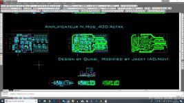
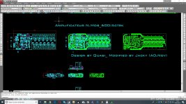
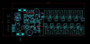
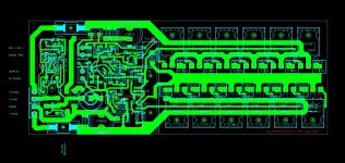
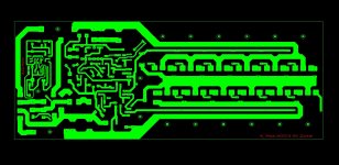
Amplifier Quasi
Hello everyone. Hello Quasi.
Well, I have to go back to sea to find and save refugees.
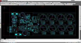
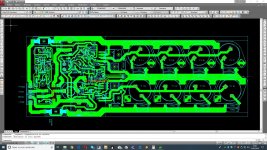
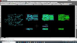
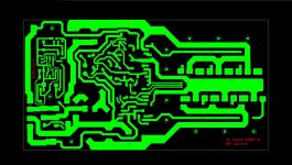
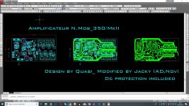
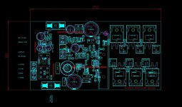
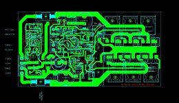
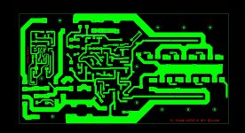
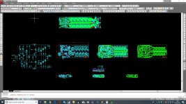
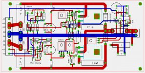
We are an NGO Emmaus, Abbé Pierre for those who know. We recycle all the electronic equipment. There is an infernal amount of material. We love HIfi. Average age 58 years. So generation Travolta and so on. We love the amp Quasi, so we worked on it very hard, I must say. Since the circuits are very similar, we tried to unify the PCBs as much as possible. See the attached files. We start building as soon as we come back from the sea campaign! Hoping to run all the amplifiers almost at best. There were some problems, but to see later. I have to go see you soon.
Jacky (ADμNov)
Hello everyone. Hello Quasi.
Well, I have to go back to sea to find and save refugees.
We are an NGO Emmaus, Abbé Pierre for those who know. We recycle all the electronic equipment. There is an infernal amount of material. We love HIfi. Average age 58 years. So generation Travolta and so on. We love the amp Quasi, so we worked on it very hard, I must say. Since the circuits are very similar, we tried to unify the PCBs as much as possible. See the attached files. We start building as soon as we come back from the sea campaign! Hoping to run all the amplifiers almost at best. There were some problems, but to see later. I have to go see you soon.
Jacky (ADμNov)
Attachments
-
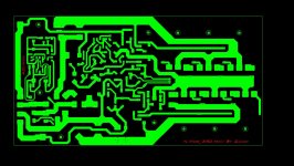
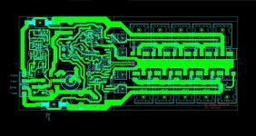
 N.Bip_Impl.jpg350 KB · Views: 627
 -
 N.Bip_Lyt.jpg399.2 KB · Views: 609
 -
 N.Bip_Pcb.jpg273.2 KB · Views: 602
 -
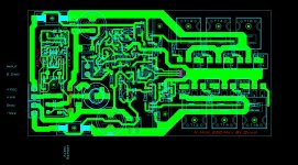
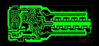
 N.Mos350Dc_Acad.jpg236.6 KB · Views: 590
 -
 N.Mos350Dc_Impl.jpg150.7 KB · Views: 218
 -
 N.Mos350Dc_Lyt.jpg245.8 KB · Views: 231
 -
 N.Mos350Dc_Pcb.jpg139.1 KB · Views: 175
 -
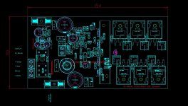
 N.Mos350MkII_Acad.jpg295.8 KB · Views: 156
 -
 N.Mos350MkII_Pcb.jpg133.5 KB · Views: 154
 -
 N.Mos350MkII_Lyt.jpg236.3 KB · Views: 168
Amplifier Quasi
Next
Next
Attachments
-
 N.Mos350MkII_Impl.jpg172.9 KB · Views: 160
 -
 N.Mos400Actrk_Acad.jpg278.6 KB · Views: 133
 -
 N.Mos400Actrk_Impl.jpg163.6 KB · Views: 116
 -
 N.Mos400Actrk_Lyt.jpg221.3 KB · Views: 123
 -
 N.Mos400Actrk_Pcb.jpg138.6 KB · Views: 120
 -
 N.Mos400Irf_Impl.jpg339.8 KB · Views: 134
 -
 N.Mos400Irf_Lyt.jpg334.2 KB · Views: 130
 -
 N.Mos400Irf_Pcb.jpg237.8 KB · Views: 105
 -
 N.Mos400Irf_ProtDc.jpg196.8 KB · Views: 109
 -
 N.Mos400Irf+_Impl.jpg151.7 KB · Views: 133
Amplifier Quasi
The end
The end
Attachments
-
 N.Mos500Dc_Acad.jpg257.8 KB · Views: 139
 -
 N.Mos500Dc_Impl.jpg209.6 KB · Views: 137
 -
 N.Mos500Dc_Lyt.jpg247.3 KB · Views: 128
 -
 N.Mos500Dc_Pcb.jpg160.7 KB · Views: 104
 -
 N.Mos600Actrk_Acad.jpg283.4 KB · Views: 110
 -
 N.Mos600Actrk_Impl.jpg197.1 KB · Views: 167
 -
 N.Mos600Actrk_Lyt.jpg272.6 KB · Views: 160
 -
 N.Mos600Actrk_Pcb.jpg141.5 KB · Views: 150
I did build this Quasi Amp 9 years ago
working fine, no issues, but much more heat dissipation compare to ACTRK400/600
I have changed to ACTRK600 its another quasi design,
much more efficient with excellent sound and reliability from same designer
working fine, no issues, but much more heat dissipation compare to ACTRK400/600
I have changed to ACTRK600 its another quasi design,
much more efficient with excellent sound and reliability from same designer
Attachments
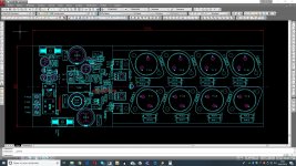
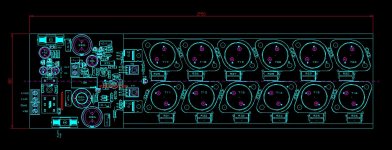
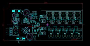
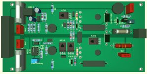
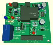
Quasi ACTRK400/600 with OP input stage
Attachments
Last edited:
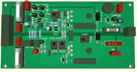
I forget
LED Status
ON Power
Signal
Clip
Clip Limiter
contact me if interested, I share Gerber and schematic
If you are using IXYS: IXTK46N50L / IXTK110N20L2
only 1 Pair Mosfets required for High Power 500 - 1000W
PCB Quasi ACTRK 600 amp is small 160 x 80 mm
IXYS: IXTK46N50L / IXTK110N20L2
LED Status
ON Power
Signal
Clip
Clip Limiter
contact me if interested, I share Gerber and schematic
If you are using IXYS: IXTK46N50L / IXTK110N20L2
only 1 Pair Mosfets required for High Power 500 - 1000W
PCB Quasi ACTRK 600 amp is small 160 x 80 mm
IXYS: IXTK46N50L / IXTK110N20L2
Last edited:
I forget
LED Status
ON Power
Signal
Clip
Clip Limiter
contact me if interested, I share Gerber and schematic
If you are using IXYS: IXTK46N50L / IXTK110N20L2
only 1 Pair Mosfets required for High Power 500 - 1000W
PCB Quasi ACTRK 600 amp is small 160 x 80 mm
IXYS: IXTK46N50L / IXTK110N20L2
Hello NMOS. Congratulations on your initiative.
I am happy to know that the Actrk600 has less heat dissipation.
Could you please share the GERBER and schematic?
I do not need much power, I have available to use the IRFP450 and IRFP460. Would you recommend any of these?
Thank you for your help. (my email: grechejr@gmail.com)
I did build this Quasi Amp 9 years ago
working fine, no issues, but much more heat dissipation compare to ACTRK400/600
I have changed to ACTRK600 its another quasi design,
much more efficient with excellent sound and reliability from same designer
Hi NMOS, just curious if the sound quality was better with the ACTRK600?
Thanks
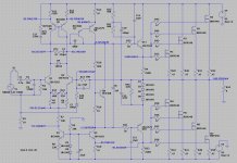
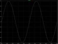
Greetings - long time no Quasi.
Anyway started playing around again, trying to improve the Nmos350 / 500. A few changes around the second stage, component values throughout and tiny bits of filtering to add more control.
This is the SIM, not perfect but not bad. Looking forward to further improving it with your ideas. SIM file plus screen shots to follow.
Attachments
I feel to much components in front end without benefits ,
op amp front end NE5534A could be better solution and more DIYer friendly,
no need matching transistors, less components
op amp front end NE5534A could be better solution and more DIYer friendly,
no need matching transistors, less components
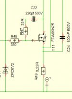
Hi Quasi,
I have build 10 years ago your NMOS
NMOS MK3 should have real impovements
1 pcs. Mosfet FDA69N25 can replace 3 -4 pcs. IRFP240, save cost and space
To improve efficiency from NMOS we should add CLass TD Rail switcher its
cheap with less components, dissipation for NMOS about 50W at fullpower compare before about 400W
1 pcs. Mosfet FDA69N25 is more enough for full output power
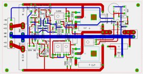
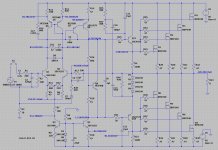
look attachment schematic tracking Downconverter
I have build 10 years ago your NMOS
NMOS MK3 should have real impovements
1 pcs. Mosfet FDA69N25 can replace 3 -4 pcs. IRFP240, save cost and space
To improve efficiency from NMOS we should add CLass TD Rail switcher its
cheap with less components, dissipation for NMOS about 50W at fullpower compare before about 400W
1 pcs. Mosfet FDA69N25 is more enough for full output power
look attachment schematic tracking Downconverter
Attachments

I forget
LED Status
ON Power
Signal
Clip
Clip Limiter
contact me if interested, I share Gerber and schematic
If you are using IXYS: IXTK46N50L / IXTK110N20L2
only 1 Pair Mosfets required for High Power 500 - 1000W
PCB Quasi ACTRK 600 amp is small 160 x 80 mm
IXYS: IXTK46N50L / IXTK110N20L2
I'm very interested in your state: "only 1 Pair Mosfets required for High Power 500 - 1000W".
Could You share Gerber and schematic?
- Home
- Amplifiers
- Solid State
- Power amp under development