Hi chico67,
I'm sorry to say, you absolutely do need an oscilloscope to figure out what is wrong here. Otherwise you're just guessing in the dark.
Do you know anyone who has access to an oscilloscope? Can you buy a used one that works, and a 10X probe?
-Chris
I'm sorry to say, you absolutely do need an oscilloscope to figure out what is wrong here. Otherwise you're just guessing in the dark.
Do you know anyone who has access to an oscilloscope? Can you buy a used one that works, and a 10X probe?
-Chris
What impedance of load are you using?
Try a high load resistance first, maybe 1000r 5W
Monitor through a cheap speaker with a 2k resistor in series to hear a quiet version of the output sinewave.
Try a high load resistance first, maybe 1000r 5W
Monitor through a cheap speaker with a 2k resistor in series to hear a quiet version of the output sinewave.
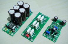
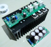
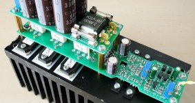
It's been a while I did not build a new amplifier.
Using SMD part and IRFP240 since i have few of them lying around
Partial finish, still waiting heatsink for the other channel.
Feed it using switching power supply @ +/-46V since my target about 200W @ 4 Ohm. It working flawless.
Thank's Quasi for your circuit
Using SMD part and IRFP240 since i have few of them lying around
Partial finish, still waiting heatsink for the other channel.
Feed it using switching power supply @ +/-46V since my target about 200W @ 4 Ohm. It working flawless.
Thank's Quasi for your circuit
Attachments
Thank's Anatech and Khalsa
BTW I'm thinking about using a Electronic DC Load (with rectifier at the amplifier output) to test this Amp working at full power since i do not have a >200W resistor as load
It is good or bad idea?
BTW I'm thinking about using a Electronic DC Load (with rectifier at the amplifier output) to test this Amp working at full power since i do not have a >200W resistor as load
It is good or bad idea?
Hi crt,
A bad idea. They are not designed for an AC signal and will try to maintain whatever current you set them up for. So not a reasonable load for an amplifier. These devices are designed for testing power supplies, not bipolar AC generators (your amplifier).
You can buy 8 ohm 100W resistors very cheaply these days. I just bought four for $15 approx. So for an 8 ohm load, use four of these per channel and you will have an 8 R load rated for 400 W. You must mount these on a heat sink of course!
I use the "proper" 8 R, non-inductive, 250 W dummy loads dictated by various audio distributors for doing amplifier repairs. Mine are probably about 30 years old now. They were expensive, each stereo set cost me $150 including the heat sinks and I bought 3 sets back then. So what I just suggested for you is amazingly cheap.
-Chris
Hello., Everyone
what's the page of final this Circuit.,
Could i try to build this amp.
Regards.
Chao
what's the page of final this Circuit.,
Could i try to build this amp.
Regards.
Chao
@Anatech
Understand, i will look's for some high power resistor at local shop.
do you have a link for your "special" load for amplifier?
100% not gonna buy it, just eager to know 🙂
@Jansaen
All his artwork is here AFAIK
Nmos Series - Quasi's DIY Audio Site
Understand, i will look's for some high power resistor at local shop.
do you have a link for your "special" load for amplifier?
100% not gonna buy it, just eager to know 🙂
@Jansaen
All his artwork is here AFAIK
Nmos Series - Quasi's DIY Audio Site
Hi,
I just searched on Ebay for this, here is the search page, look down a little bit.
8 ohm dummy load | eBay
The resistors at the top are better and do not require a heat sink, but they do cost more.
The resistors I was talking about were bought off Amazon and are the same things. I'll try a search there.
100W 8 Ohm Screw Tap Mounted Aluminum Housed Wirewound Resistors 2 Pcs: Amazon.ca: Tools & Home Improvement
These are all available in 4 ohm as well. Pretty cheap if you ask me.
-Chris
Here's my PCB layout.
It is better to use original layout that quasi already made for us
which is proven/guaranteed to work.
@Anatech
Thank you for the link 🙂
It is better to use original layout that quasi already made for us
which is proven/guaranteed to work.
@Anatech
Thank you for the link 🙂
Attachments
I am looking for a topology to use two of these FETs in an output stage. The amp in this thread looks like a possible topology.
Here is the power FET
http://ixapps.ixys.com/DataSheet/DS100728A(IXTN660N04T4).pdf
The intent is to have an amplifier that can supply unlimited current at low voltage.
I have zero amp design skills and zero pcb layout skills. I can characterize the devices and build amps and buy boards and parts.
Is anyone from this thread interested in participating?
Hi crt,
Sorry, missed your reply. I found this link at Digikey. Good for information only.
HS250 8R F Ohmite | Resistors | DigiKey
At Mouser:
NH2508R000FJ01 Vishay / Dale | Mouser Canada
silly price!
HS250 8R F ARCOL / Ohmite | Mouser Canada
Much better. They haven't gone up in over 30 years, so these are a real bargain!
If anyone goes this route, the heat sink must be milled flat to mount the resistor. After blowing one up, my load assembly is getting temperature readouts installed. I have nearly burned them out on a few occasions. You know that when you get that funny hot electronics smell from the load heat sink.
Aside from the lower prices on these than I expected, I feel they are well worth the money if you ever have to make a power measurement that has to be accepted by any manufacturer, distributor or anyone else in the audio field. They are a standard.
-Chris
-Chris
if you want more then 125 watts, Class D becomes the only way to go.
stability compensation, Distortion, bias current and output waste heat become troublesome.
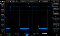
I getting 75w RMS out of my amp with 40 volt rails at .0002% distortion
on the schematic R20 R21 R22 should all be equal.
More importatly T9 and T10 should be connected to the rails after the fuse. Currently the driver will destroy the mosfets by popping the gate voltage if either 5A fuse blows.
stability compensation, Distortion, bias current and output waste heat become troublesome.
I getting 75w RMS out of my amp with 40 volt rails at .0002% distortion
on the schematic R20 R21 R22 should all be equal.
More importatly T9 and T10 should be connected to the rails after the fuse. Currently the driver will destroy the mosfets by popping the gate voltage if either 5A fuse blows.
Last edited:
Hi stocktrader200,
I strongly disagree with you on your point of view. I would say that class "D" is one way to go, you are claiming that it's the only way that makes sense. Your statement being too exclusive really.
-Chris
A personal opinion. The technology isn't what the thread is about for one. Also, class "D" hasn't reached a level good enough for listening at home, although it appears that you have settled quite happily for it.if you want more then 125 watts, Class D becomes the only way to go.
stability compensation, Distortion, bias current and output waste heat become troublesome.
I getting 75w RMS out of my amp with 40 volt rails at .0002% distortion
I strongly disagree with you on your point of view. I would say that class "D" is one way to go, you are claiming that it's the only way that makes sense. Your statement being too exclusive really.
Probably not true, measured performance to be honest with you. Plus, you need a special filter in order to get any reading due to the switching transients that good instrumentation will pick up.I getting 75w RMS out of my amp with 40 volt rails at .0002% distortion
-Chris
For a dummy load, how about enough extension cord to get the resistance you're looking for. Get some long and thinner guage and use all the wires in series as one conductor
check this out, Revisiting some "old" ideas from 1970's - IPS, OPS , A brilliant design with matched transistors from a lot of 100 pnp and npn. I set my gain at 10 as well ( 20 db )
regulated VAS rails and mosfet outputs the distortion numbers are very low.
regulated VAS rails and mosfet outputs the distortion numbers are very low.
Last edited:
- Home
- Amplifiers
- Solid State
- Power amp under development