AndrewT said:Hi,
for fear of stepping on Quasi's toes,
I thought my foot hurt.....Lol
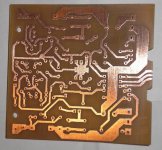
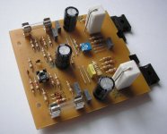
Finished Nmos 200
I'll test it later this week.
Domestic hifi only folks, please. If you want more grunt build the larger boards, or if your thinking PA bigger check out my other amp http://www.diyaudio.com/forums/showthread.php?postid=991050#post991050
Cheers
Quasi
I'll test it later this week.
Domestic hifi only folks, please. If you want more grunt build the larger boards, or if your thinking PA bigger check out my other amp http://www.diyaudio.com/forums/showthread.php?postid=991050#post991050
Cheers
Quasi
Attachments

 beautifull ...... work of art
what size of heatsink you will use ? and what power transformer ?
To220 has the same power with my To247 that i've just started ?
Re[01]: Finished Nmos 200
As always fine building and PCB technique by the quasi GOD.
This board size reminds me of my Sinclair Z-30 amplifier modules and they used a flat metal heatsink plate for the TO-126 like trainistors. I built my Sinclar amp some 35+ years ago. I actually still have them in the real Sinclair metal case after building a walnut veenier case initially with VU meters. The PSU developed some sort of problem blowing normal fuses and I have never had time to sort out why i.e. if a PSU issue or one of the modules. Slow blow fuses did not blow, but I never leave the slow blow fuses in. I have all the schematics and voltages somewhere in my filing cabinet. One of these years. 😉
Definition please 😉 Is this the broomstick, vaccum cleaner, laundry, cook, etc builder? Perhaps they are making a silicon stew?
Regards,
John L. Males
Willowdale, Ontario
Canada
22 January 2007 19:25
quasi said:I'll test it later this week.
As always fine building and PCB technique by the quasi GOD.
This board size reminds me of my Sinclair Z-30 amplifier modules and they used a flat metal heatsink plate for the TO-126 like trainistors. I built my Sinclar amp some 35+ years ago. I actually still have them in the real Sinclair metal case after building a walnut veenier case initially with VU meters. The PSU developed some sort of problem blowing normal fuses and I have never had time to sort out why i.e. if a PSU issue or one of the modules. Slow blow fuses did not blow, but I never leave the slow blow fuses in. I have all the schematics and voltages somewhere in my filing cabinet. One of these years. 😉
Domestic hifi only folks, please.
Definition please 😉 Is this the broomstick, vaccum cleaner, laundry, cook, etc builder? Perhaps they are making a silicon stew?
Regards,
John L. Males
Willowdale, Ontario
Canada
22 January 2007 19:25
marus said:... And i don't understand why i'll put 4A fuse and 20A MosFET(you know what i mean 😀)
Cheers
If a 4 amp fuse blows as a result of a fault condition, generally the 20 amp mosfet is blown too. The fuse is really the last line of defence and will not protect your amp module (this is probably already dead) but hopefully will stop other damage (fires etc). The only way to protect the output mosfets from external abuse is via overcurrent detection and electronic (not thermal) control.
Cheers
Q
Re: Re[01]: Finished Nmos 200
Maybe they should only be installed in white enamel cases....
keypunch said:Definition please 😉 Is this the broomstick, vaccum cleaner, laundry, cook, etc builder? Perhaps they are making a silicon stew?
Maybe they should only be installed in white enamel cases....
No, I mean if a current of 4A pass trough 4A fuses they will blow and we never have more than 4A on Mosfets .... So , why that waste of 20A Mosfets ?
marus said:No, I mean if a current of 4A pass trough 4A fuses they will blow and we never have more than 4A on Mosfets .... So , why that waste of 20A Mosfets ?
Unfortunately that's not how fuses work, i.e; a normal 4 amp fuse will not blow when it passes 4 amps, it may not blow passing 5 amps either. The same fuse passing say 6 amps or so might take more than 10 seconds to blow and around 1 second passing 10 amps. So what, it is still under 20 amps, you may ask?
Well if the Mosfet has 100v across it and a fault condition causes 10 amps to pass through it, this FET is now trying to dissipate 1000 watts and 1 second is probably too long. It might be better that a dead short is experienced and the fuse is destroyed almost instantly, but even this is generally too slow for the potentially ten thousand watts of instantaneous dissipation inside the poor old FET.
In normal operation we still go for "20 amp Mosfets" to get the power capability we require with respect to the SOAR of the FET. Remember even with just 50 volts across the FET, 4 amps means 200 watts.
So please consider fuses as the defence of last resort.
Cheers
Q
marus said:my PCB ... 🙄
Cool, what are the notches at the end for? Good luck with the build.
Cheers
Hi,
the rail fuses are there for medium to long term protection, just as the heatsink is starting to get hot.
Prior to that, the electronic current limit is operating to just keep the output devices INSIDE their SOAR but the disspation at the limiting current causes rapid overheating.
Continued heating will bring the SOAR down to meet and then pass the limiting current value. Then the output stage blows.
The chosen fuse must blow before the Tc rises above the acceptable temperature chosen for the current limit and SOA.
as an example;
limiting current about 8A.
Vrail +-60V each transistor will dissipate 480W for a half (square wave) cycle. the heatsink will heat very rapidly.
Fuse blows within 200mS to 1S.
I use a fast fuse rated at half peak current into minimum rated load.
Vrail=60V and 4ohm speakers Ipk~=56/4=14Apk, fuse =F7A
and due to time delay in a fast fuse they never cause nuisance blowing and very loud music. Fusing this way even allows full power testing into rated load (due to halfwave rms value).
Hi,
input pair in the LTP.
parallel sets in the output stage.
The upper and lower sets in the output stage do not need to be matched.
Any other candidates?
input pair in the LTP.
parallel sets in the output stage.
The upper and lower sets in the output stage do not need to be matched.
Any other candidates?
I don't have sets, i have just one pair of IRFP460 in the output stage
I say : T1-T5 , T9-T10 and of course the mosfet pair T11-T12 .....
I say : T1-T5 , T9-T10 and of course the mosfet pair T11-T12 .....
Hi guys,
I have to confess some stupid thing I have done and stayed alive. I short circuit my quasi amp, and the only thing that was blown was 5A fuses on board!!!
I replace the fuses and amp works fine again.
I couldn't belive! I make apology to my amp and we are friends again😀 ...
Cheers!!!
I have to confess some stupid thing I have done and stayed alive.
I short circuit my quasi amp, and the only thing that was blown was 5A fuses on board!!! I replace the fuses and amp works fine again.
I couldn't belive! I make apology to my amp and we are friends again😀 ...
Cheers!!!
pejinm said:Hi guys,
I have to confess some stupid thing I have done and stayed alive.
I replace the fuses and amp works fine again.
I couldn't belive! I make apology to my amp and we are friends again😀 ...
Cheers!!!
 don't do it again.
Hi all,
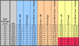
I have updated the Table of Post # 285 to include the R6 value based on Vrail and fusing for the required load power in my comments of Post #1190.
Please note that the above referenced table has been reposted as is a few times in the thread. I do not have the time to find those postings to list them in reference to the updated table attached with the fusing and R6 columns added.
I have used Andrew's suggested method in Post #1451 to calculate fusing.
Please note that this table does not agree with quasi's recommended fusing shown on the quasi PCB layouts. Quasi's recommended fusing for 6 FETs for 4 ohms is 5 Amps, for the 10 FETs for 4 ohms is 10 Amps and the 4 TO-220s/2 TO-247s based design of 4 Amps which I believe is fusing rated for 4 ohms. I am not sure if quasi's fuse recommendations are based on using slow blow fuses, which may account for the lower fuse rating quasi suggests.
Regards,
John L. Males
Willowdale, Ontario
Canada
26 January 2007 19:57
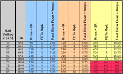
26 January 2007 20:10 Opps, updated chart to exclude fusing for the "NO" configurations. jlm
26 January 2007 20:12 Typo corrections
26 January 2007 20:14 Typo correction
26 January 2007 20:15 Typo correction
26 January 2007 20:21 Updated chart to mark "NO" areas out in red
P.S. I am still researching the thread for specifications on the quasi amp. I decided in the process that I wanted the table updated so I do not end up amending the specifications posting and the posting I made a few weeks back about the current schematics, PCBs, et al for which this same above noted table was referenced.
I have updated the Table of Post # 285 to include the R6 value based on Vrail and fusing for the required load power in my comments of Post #1190.
Please note that the above referenced table has been reposted as is a few times in the thread. I do not have the time to find those postings to list them in reference to the updated table attached with the fusing and R6 columns added.
I have used Andrew's suggested method in Post #1451 to calculate fusing.
Please note that this table does not agree with quasi's recommended fusing shown on the quasi PCB layouts. Quasi's recommended fusing for 6 FETs for 4 ohms is 5 Amps, for the 10 FETs for 4 ohms is 10 Amps and the 4 TO-220s/2 TO-247s based design of 4 Amps which I believe is fusing rated for 4 ohms. I am not sure if quasi's fuse recommendations are based on using slow blow fuses, which may account for the lower fuse rating quasi suggests.
Regards,
John L. Males
Willowdale, Ontario
Canada
26 January 2007 19:57
26 January 2007 20:10 Opps, updated chart to exclude fusing for the "NO" configurations. jlm
26 January 2007 20:12 Typo corrections
26 January 2007 20:14 Typo correction
26 January 2007 20:15 Typo correction
26 January 2007 20:21 Updated chart to mark "NO" areas out in red
P.S. I am still researching the thread for specifications on the quasi amp. I decided in the process that I wanted the table updated so I do not end up amending the specifications posting and the posting I made a few weeks back about the current schematics, PCBs, et al for which this same above noted table was referenced.
Attachments
keypunch said:Hi all,
I have updated the Table of Post # 285 to include the R6 value based on Vrail and fusing for the required load power in my comments of Post #1190.
Please note that the above referenced table has been reposted as is a few times in the thread. I do not have the time to find those postings to list them in reference to the updated table attached with the fusing and R6 columns added.
I have used Andrew's suggested method in Post #1451 to calculate fusing.
Please note that this table does not agree with quasi's recommended fusing shown on the quasi PCB layouts. Quasi's recommended fusing for 6 FETs for 4 ohms is 5 Amps, for the 10 FETs for 4 ohms is 10 Amps and the 4 TO-220s/2 TO-247s based design of 4 Amps which I believe is fusing rated for 4 ohms. I am not sure if quasi's fuse recommendations are based on using slow blow fuses, which may account for the lower fuse rating quasi suggests.
Regards,
John L. Males
Willowdale, Ontario
Canada
26 January 2007 19:57
26 January 2007 20:10 Opps, updated chart to exclude fusing for the "NO" configurations. jlm
26 January 2007 20:12 Typo corrections
26 January 2007 20:14 Typo correction
26 January 2007 20:15 Typo correction
26 January 2007 20:21 Updated chart to mark "NO" areas out in red
P.S. I am still researching the thread for specifications on the quasi amp. I decided in the process that I wanted the table updated so I do not end up amending the specifications posting and the posting I made a few weeks back about the current schematics, PCBs, et al for which this same above noted table was referenced.
Hi All,
Sorry, one last update to the table so the headings do not bleed into the borders. I managed to find where the setting was to control this after looking a few times earlier.
Regards,
John L. Males
Willowdale, Ontairo
Canada
26 January 2007 20:33
Attachments
Hi Jonh,
5A fuseses on my board were just found very useful.
It's been proved to be the last defence from short circuiting the amp. I replace the fuses with same value, for just in case.
Regards...
5A fuseses on my board were just found very useful.
It's been proved to be the last defence from short circuiting the amp. I replace the fuses with same value, for just in case.
Regards...
Hi Pejinm,
Did you use fast or slow type fuses? Rail voltage and speaker load for your amps?
The chart I posted is certainly open to revision. For sure if one's normal music listening levels are typically in and about the 1W-5W RMS range then the fusing from the chart can likely be reduced by about 35% - 40% I would guess.
Thanks for your feedback.
Regards,
John L. Males
Willowdale, Ontario
Canada
27 January 2007 06:55
27 January 2007 06:56 Added rail and load question
- Home
- Amplifiers
- Solid State
- Power amp under development