Do they need to be 5 watt?
Hi Andrew,
A 5 watt resistor dissipating only 2 watts gets very hot. Consider also the ambient temperature inside an amp. Then regard has to be given to availability. The perfect resistor might be a 3 watt type, but this is not likely to be stocked by the local electronics store and could well cost more than a 5 watt. Note that in my TO220 amp, I opted for 2 x 2 watt resistors. These cost me about 15 cents each, and around here I can buy a 5 watt for between 25 and 30 cents.
Cheers
Quasi
marus said:Hey , what class is this amp ? 😕
This is a quasi-complementary class AB amplifier.
Cheers
Q
Hi Quasi,
the main point of post1420 was that except for full power testing these resistors NEVER run continuously at anywhere near full power rating.
They are ticking over at 0.1mW to a few tens of mW.
If cost or availability were the selection criteria, then parallel sets of 1% 500mW or 600mW metal film or 5% 250mW carbon film win out every time.
AndrewT said:Hi Quasi,
the main point was that except for full power testing these resistors NEVER run continuously at anywhere near full power rating.
They are ticking over at 0.1mW to a few tens of mW.
If cost or availability were the selection criteria, then parallel sets of 1% 500mW or 600mW metal film or 5% 250mW carbon film win out every time.
Yes you're right Andrew of course but as a designer I have to make decisions about layout (I hate drilling holes). The resistor (resistors) also have to handle current as well and some small resistors just aren't up to it. So whilst the average dissipation is low momentary dissipation can create issues. A bass note for a second or so at near clipping can surpass the momentary dissipation of smaller resistors.
The larger surface area of bigger resistors also mean lower localised temperatures (I also hate browning PCBs).
I have actually thought of making my own "low inductance" resistors using multiple 1/2 watt metal films....but that's another story.
Cheers
Q
Order just going out...
Hello,
My parts-order for the NMOS200 (To220 Version) has just gone out.
I like the idea of using 2W metalfilm (I pay 9 eurosent for the 2W and 8 for the 0,25W), they are easy to get and very inexpensive.
I will solder them with a bit of distance to the pcb allowing the air flowing around them (I hate browning pcbs too).
As I will order my semiconductors from a different source, I still dont know which mosfet to use. My last decision was to use the IRF640N .
Quasi, maybe you've already tested your prototype with irf840?
I'm looking forward to build this amp. I've got an 500VA torroid lying around for years, now I found a suitable amp for it.
Greetings.
Black
quasi said:The resistor (resistors) also have to handle current as well and some small resistors just aren't up to it.
Is this only when one uses a smaller dimensioned resistor as Andrew may be proposing as opposed to using as many resistors in parallel to make, for example, a 5W resistor?
The larger surface area of bigger resistors also mean lower localised temperatures (I also hate browning PCBs).
I seems to me using smaller wattage resistors in parallel to "make" the desired wattage would actually be increasing the surface area when one uses 1W or 2W resistors.
Using 500mw or so resistors in parallel generally would have less surface area than for example a 5W. True?
I have actually thought of making my own "low inductance" resistors using multiple 1/2 watt metal films....but that's another story.
My intention with your design is to use multiple (5x) 1W or (3X) 2W resistors to avoide the inductance of the most commonly availoable 5W resistors. As side benefit there will be more surface area to disapate and cool the resistors. The other reason was to be able to use carbon resistors for the source resistors as it seem many seem to feel carbon resistors have an endearing audio quality and the output stage devices will not have much resistor noise injected due to the signal level in an output stage.
Cheers
Q
Quasi,
BTW I have been working on the summary via prior postings in thread for the specs and performance of the amp. It is a very time consuming process even with my knowledge of the thread since almost the start of the thread. Not big deal, just takes time and in end I feel it is worth if for many reasons. So bear with me as I am making good progress. The actual thread posting does not take alot of time, just the search and review part does.
Regards,
John L. Males
Willowdale, Ontario
Canada
21 January 2007 09:59
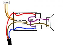
I don't see where is the POWER GND
You know ... from thw power supply go out 3 wires : +50V , GND, -50V
So.... where on PCB is GND ?
You know ... from thw power supply go out 3 wires : +50V , GND, -50V
So.... where on PCB is GND ?
Marus,
You'll have to use the Speaker-GND pin on the PCB fpr both GND.
So I'll use the gnd Pin for the incomimng PSU wire and the outgoing Speaker-wire.
Alternatively you could only apply the incomimg GND (from PSU) to the PCB and get your speaker GND from your star-ground.
Greetings
You'll have to use the Speaker-GND pin on the PCB fpr both GND.
So I'll use the gnd Pin for the incomimng PSU wire and the outgoing Speaker-wire.
Alternatively you could only apply the incomimg GND (from PSU) to the PCB and get your speaker GND from your star-ground.
Greetings
Hi,
this posted PCB does not have a PCB star ground.
Create a floating central star ground (Central Audio Ground) and take all the other grounds and returns to it including the signal ground and decoupling grounds from the PCB.
this posted PCB does not have a PCB star ground.
Create a floating central star ground (Central Audio Ground) and take all the other grounds and returns to it including the signal ground and decoupling grounds from the PCB.
Hi,
is that 10r on the PCB linking signal ground to decoupling ground?
If so, then that is the short route low impedance connection for HF across the PCB.
You can add a direct wire link from the RCA ground to the floating Central Audio Ground (esure the RCA ground is isolated from chassis).
Also bring the PSU 0v common to CAG and
the Zobel return to CAG and
the safety earth disconnecting network to CAG (one for each channel) and
transformer centre tap to CAG.
Yes Marus, this is it, how I meant doing it. I did all my Amps that way and never had a problem.
Is it really better to get the speaker-Gnd from the central-GND?
Greetings
Black
Is it really better to get the speaker-Gnd from the central-GND?
Greetings
Black
Hi,
very much better to take the speaker return back to CAG and not back to the PCB.
It is alo better to take the Zobel return back to the CAG rather than the PCB, but most designs have the Zobel on board.
very much better to take the speaker return back to CAG and not back to the PCB.
It is alo better to take the Zobel return back to the CAG rather than the PCB, but most designs have the Zobel on board.
Re: Post #168 and Post #Post #1408
Quasi,
As I continue to dig out the spec information of the thread I discovered your comments in Post #168. If I decide to use a seperate, not regulated, PSU for the driver and input from the same transformer secondaries as the output stage would I assume I would be perserving the negative side R22 reference requirement whilst not changing any other intent of your design? I know taking this approach will not provide the extra 10P-P/7VRMS the front end would require to accomodate the output stage losses. That is ok. It just seems like it would be a simple and little extra cost.
I do not think it would be worth a seperate transformer of slightly higher voltage to have a regulated PSU of same secondary voltage as the output stage. I do not know as the output load impedance decreases causing well known additional losses if having a regulated PSU for the front end would cause some of the same issues you discovered when trying to find an acceptable behaviour of the amp when being driven close to rail voltages.
Samuel,
I think the above comments by quasi on the current design may be important with respect to your Post #1408 for a regulated PSU for the front end. If you have not read the thread from start then it may be worth you doing so. If you have maybe it would be worth reading again as I have happened to while searching for the sprinkled postings about the specs which has driven my abobe question to quasi which is simpler andavoids an extra transformer or need for second pair of secondaries on a single transformer. Quasi spent alot of time and effort in trying to have the amp meet his design objectives from a split PSU of +-60 and +-70 for the front end and output section respectively. It was the split PSU design that quasi initially started with and later found was not as good as a single supply design.
In my question above I am hoping for the lottle extra cost there will be a bit of the virtues of the split PSU design, i.e. some isolation from the artifacts that may occur from the output devices interaction with the main PSU.
Regards,
John L. Males
Willowdale, Ontario
Canada
21 January 2007 17:08
quasi said:
The cct you posted is for a complimentary amp not a quasi-complimentary amp. I cannot run a seperate rail for the negative side because in my cct R22 (220 ohm) must be tied to the same negative rail as the source of the negative rail FETs. This is because the gate voltage on R22 is referenced from the negative rail. If I split this rail I lose the reference. This was covered near the beginning of this thread.
Cheers
Quasi,
As I continue to dig out the spec information of the thread I discovered your comments in Post #168. If I decide to use a seperate, not regulated, PSU for the driver and input from the same transformer secondaries as the output stage would I assume I would be perserving the negative side R22 reference requirement whilst not changing any other intent of your design? I know taking this approach will not provide the extra 10P-P/7VRMS the front end would require to accomodate the output stage losses. That is ok. It just seems like it would be a simple and little extra cost.
I do not think it would be worth a seperate transformer of slightly higher voltage to have a regulated PSU of same secondary voltage as the output stage. I do not know as the output load impedance decreases causing well known additional losses if having a regulated PSU for the front end would cause some of the same issues you discovered when trying to find an acceptable behaviour of the amp when being driven close to rail voltages.
Samuel Jayaraj said:Further, either the front end should have its own regulated supply which is about 5 volts higher or decouple the power rails of the stage preceding the driver stage with a series connected diode/resistor with its own decoupling.
Samuel,
I think the above comments by quasi on the current design may be important with respect to your Post #1408 for a regulated PSU for the front end. If you have not read the thread from start then it may be worth you doing so. If you have maybe it would be worth reading again as I have happened to while searching for the sprinkled postings about the specs which has driven my abobe question to quasi which is simpler andavoids an extra transformer or need for second pair of secondaries on a single transformer. Quasi spent alot of time and effort in trying to have the amp meet his design objectives from a split PSU of +-60 and +-70 for the front end and output section respectively. It was the split PSU design that quasi initially started with and later found was not as good as a single supply design.
In my question above I am hoping for the lottle extra cost there will be a bit of the virtues of the split PSU design, i.e. some isolation from the artifacts that may occur from the output devices interaction with the main PSU.
Regards,
John L. Males
Willowdale, Ontario
Canada
21 January 2007 17:08
Tomorow i go to buy the components for Quasi Nmos with one pair of IRFP460... 😀
I have a few more questions :
1. What purpose have T8 and how i hold it on the heatsink when he doesn't have a hole ?
2. How many uF must have the power source filter ? (for 100W, 8ohm, +/-50V)
3. What adjustments i must make after the pcb+components are ready ? Especially those trimers VR1 and VR2 , how i set them ?
... And i don't understand why i'll put 4A fuse and 20A MosFET (you know what i mean 😀)
Cheers
I have a few more questions :
1. What purpose have T8 and how i hold it on the heatsink when he doesn't have a hole ?
2. How many uF must have the power source filter ? (for 100W, 8ohm, +/-50V)
3. What adjustments i must make after the pcb+components are ready ? Especially those trimers VR1 and VR2 , how i set them ?
... And i don't understand why i'll put 4A fuse and 20A MosFET
(you know what i mean 😀)Cheers
Hi quasi,
thank you for sharing the design.
I'd like to build 3 quasi version with 3prs (irfp 250), 2prs (2sk2915) and 1 pr (IRFP 460).
please give me some advice about my tr choice.
Is there any chance for pcb with 1 pair outpot transistor + protection?
mnay tks.
best rgds,
thank you for sharing the design.
I'd like to build 3 quasi version with 3prs (irfp 250), 2prs (2sk2915) and 1 pr (IRFP 460).
please give me some advice about my tr choice.
Is there any chance for pcb with 1 pair outpot transistor + protection?
mnay tks.
best rgds,
dexter said:Hi quasi,
Is there any chance for pcb with 1 pair outpot transistor + protection?
mnay tks.
best rgds,
Dexter,
You have a few choices,
1) If you are building a stereo pair you can use the PCB for two DC protection circuits on one PCB quasi posted.
2) Use the 2 pair mini PCB posted in recent weeks in a two TO-220 pair or single TO-247 pair version ago with the standalone DC protection PCB quasi posted some months ago.
3) Use the 2 pair PCB with DC protection I posted a couple weeks ago and only use one pair on the board.
4) If you can be patient for a week or so I can convert the 1 Pair version of the "classic" quasi PCB with DC Protection. I need to first complete an outstanting request for my thread research on the specs for the amp module first. This research task has made excellent progress, but I am only half way through the thread in my research. This means it is likely at least 2 weeks before i have converted the PCB so I post it to diyAudio.
5) I have a single pair version of the "classic" board with DC Protection on the web site I posted just tad over year ago. Please use white out or a graphics editing program to remove the extra trace about VR2 error Shawn discovered in Aug or early Sept of last year. Quasi corrected those errors for the 3 and 5 pair version shortly thereafter. The boards I derived a bit over a year ago had this PCB VR2 related trace error also had the error. I have only had some time to redo those derived boards late this past fall, but no time to post the revised boards to the site. Due to a diyAudio attachment limit of 100K, it takes alot of effort for me to find a way to reduce the versions of the boards I derive in order to post them to the forum. I do not have any PCB CAD software, let alone the one quasi uses. The result of that is I have to convert the the PCBs to a graphic file which takes up far more space than the vector based data embedded in the PDF PCB files quasi posts from his PCB CAD software.
Regards,
John L. Males
Willowdale, Ontario
Canada
21 January 2007 21:21
marus said:Tomorow i go to buy the components for Quasi Nmos with one pair of IRFP460... 😀
I have a few more questions :
1. What purpose have T8 and how i hold it on the heatsink when he doesn't have a hole ?
2. How many uF must have the power source filter ? (for 100W, 8ohm, +/-50V)
3. What adjustments i must make after the pcb+components are ready ? Especially those trimers VR1 and VR2 , how i set them ?
... And i don't understand why i'll put 4A fuse and 20A MosFET
Cheers
1. T8 is used to track the temperature of the heatsink and reduces the bias current as the heatsink warms up. On the Nmos200 it mouns in a hole on the heatsink bracket. On the Nmos350 & 500 it mounts under the PCB in a hole drilled in the heatsink. Alternatively a TO126 transistor can be used with fly leads back to the PCB.
2. I suggest 10,000uF per rail per module. Use 63v capacitors.
3. Below is a brief setup description:
The setup is done without a load connected to the power amp module. First check your work and make sure output devices are insulated from heatsink.
Remove fuses and replace with 100 ohm 5 watt resistors (I solder the resistors to old blown fuses)
Make sure power supply polarity is correct. Connect amp to power supply and turn on.
Check output offset voltage and adjust VR1 to achieve an offset of less than 10 mV.
All being well a place a voltmeter across one of the 100 ohm resistors.
Adjust VR2 to set the output stage bias current, by measuring the voltage across one of the 100 ohm resistors. For a 4 FET board set for a voltage of 6 volts. For a 2 FET board adjust for 3 volts. This equates to a bias current of 30mA per FET pair .
All being well replace the 100 ohm resistors with 10 ohms 1 watt resistors and re-adjust VR2 to get 0.6 volts for the 4 FET board or 0.3 volts for the 2 FET board.
Once done, remove the resistors and put the fuses in. Re-check the offset voltage and adjust with VR1 if necessary. The amp is ready.
If any of the above is not understood please get a more experienced friend to help otherwise happy building and good luck with your amp.
dexter said:Hi quasi,
thank you for sharing the design.
I'd like to build 3 quasi version with 3prs (irfp 250), 2prs (2sk2915) and 1 pr (IRFP 460).
please give me some advice about my tr choice.
Is there any chance for pcb with 1 pair outpot transistor + protection?
mnay tks.
best rgds,
Thank you, it's my pleasure.
Regarding your FET choice, it depends on the power supply voltage rails you are going to use. But they look like good candidates.
Regarding the 2 FET board, it looks like John is going to help there.
Cheers
Hi,
for fear of stepping on Quasi's toes, I am resistant to suggesting this, but I must be consistent.
Aim for a PSU RC time constant at least one octave below the input DC blocking filter RC time constant.
If the input is set to 40mS then +-10mF/ch & 8ohm gives 80mS and matches Quasi's recommendation.
If you want good unattenuated bass then aim for 80 to 90mS at the input and this requires +-20mF/ch & 8ohms.
If at a later date you change to 4ohm speakers then you have to double the PSU capacitance or raise the input filter one octave.
- Home
- Amplifiers
- Solid State
- Power amp under development