Hey Rajeev;
I see a lot of N-channel amps with the resistors on the drain (or collector) of the negative supply FET so it is seems ok to do.
But these amps would not have the benefit of the local feedback and the amp is no longer truly symmetrical. For true symmetry the resistors must be on the source just as it is on the positive rail fet.
On complimentary amps (npn / pnp) the resistors are usually found on the source, the same should apply to quasi-complimentary amps.
But at the end of the day, whether it makes a big difference in the sound (or specs) is something you need to build and try.
With respect to the protection, this would only be slightly more complicated with the addition of just one more transistor.
Cheers
PS. I think my moniker "Quasi" suits me ...what do you think ? ha ha ha 🙂
It works !!!
IT WORKS! ...Whoooohooo!
It works.
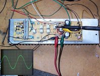
CRO shows a 10 Khz waveform into an 8 ohm resistive load at 86 volts pk to pk (around 110 watts).
Now I'll make another one for the other channel.
Still to come is the power supply, soft turn on cct, and a case. In the final configuration it will deliver 200 watts into 8 ohms and about 350 watts into 4 ohms.
But hey IT WORKS !
Cheers
IT WORKS! ...Whoooohooo!
It works.
CRO shows a 10 Khz waveform into an 8 ohm resistive load at 86 volts pk to pk (around 110 watts).
Now I'll make another one for the other channel.
Still to come is the power supply, soft turn on cct, and a case. In the final configuration it will deliver 200 watts into 8 ohms and about 350 watts into 4 ohms.
But hey IT WORKS !
Cheers
Attachments
Have you any detailed pic of square wave ( 10 kHz ) into eight Ohm ? Or eight Ohm with parallel 100 n cap ? 3 dB bellow clipping ?
Thanks;
Thanks Upupa Epops & Rajeev Luthra
I feel more relief than anything.
I will do these tests when I finish the planned power supply. The test was done using my bench supply and it's only good for about 100 watts. If I do demanding tests with this power supply I know I will get poor results.
So I have to wait until the new power supply is built.
Thanks & Cheers
Thanks Upupa Epops & Rajeev Luthra
I feel more relief than anything.
Have you any detailed pic of square wave ( 10 kHz ) into eight Ohm ? Or eight Ohm with parallel 100 n cap ? 3 dB bellow clipping ?
I will do these tests when I finish the planned power supply. The test was done using my bench supply and it's only good for about 100 watts. If I do demanding tests with this power supply I know I will get poor results.
So I have to wait until the new power supply is built.
Thanks & Cheers
Update; Power Supply
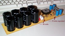
Ok...One of the power supply boards is complete (there will be one for each amp module).
Rails are +/- 60 volts for the output stage and regulated +/- 70v for the input and driver stages.
Ready now to connect one completed amp module with one completed power supply board.
Cheers
Ok...One of the power supply boards is complete (there will be one for each amp module).
Rails are +/- 60 volts for the output stage and regulated +/- 70v for the input and driver stages.
Ready now to connect one completed amp module with one completed power supply board.
Cheers
Attachments
quasi amp
Hi quasi,
Glad to hear that your amp comes to life and feels well. Could you post you final circuit diagram and that of the power supply as well when you are ready and happy with everything? I'll keep it in my collection and maybe one day build a quasi amp as well after so many years - especially if some progerss was made in two stage designes as advocated by Olssen.
Cheers,
Hey Janusz
Long time no hear. I have a few mods to make to the amp and the power supply. I'll update soon.
Cheers
🙂
Long time no hear. I have a few mods to make to the amp and the power supply. I'll update soon.
Cheers
🙂
Hello Quasi!
I'v been following this post for quite a while now, and i think congratulations are in order, now that the amp has taken physical form, and is working!
and so to my question: have you tesed any music with it yet? and if yes, how would you deffine the sound characteristics?
I was thinking of maby copying the amp myself, as i'm feling that I am ready to take another step over the gainclone stage of diy amps.
cheers
marius
Hey Demogorgon;
Thanks for your kind words.
Only sine waves have passed through the amp module at this stage. There are some small changes that I have to make to it and the power supply.
I tried to make a simple transistor regulator for the +/- 70 volt rails but the cct's performance is unsatisfactory. I'm going to use 3 terminal regulators now and these boards are being made tonight.
I think it will still be 2 weeks or so before it plays any music.
You are most welcome to build this amp. When the amp is completed and I am happy with everything then I will post all the ccts and layouts for anyone who is interested.
Cheers
High Voltage Regulator
After trying a few different regulator ccts (including basic transistor / zener ccts) I have settled on this one.
2 of these (one for each module) will supply the regulated +/- 70v to the input and driver stages of the amplifier.
Anyway cct is attached.
Cheers
After trying a few different regulator ccts (including basic transistor / zener ccts) I have settled on this one.
2 of these (one for each module) will supply the regulated +/- 70v to the input and driver stages of the amplifier.
Anyway cct is attached.
Cheers
Attachments
Re: High Voltage Regulator
Perhaps a stupid question : why not using 7824 and 7924.? Or a "floating" LM317?quasi said:After trying a few different regulator ccts (including basic transistor / zener ccts) I have settled on this one.
2 of these (one for each module) will supply the regulated +/- 70v to the input and driver stages of the amplifier.
Anyway cct is attached.
Cheers
Hey Elso Kwak;
By adjusting the value of the zeners this cct will of course work with any 3 pin regulator. I have plenty of 7812 & 7912 so that is what I'm using for this project.
I thought about a 317 but I liked the idea of locking the reference with zeners rather than resistors.
That's just personal preference I suppose.....
Cheers
Perhaps a stupid question : why not using 7824 and 7924.? Or a "floating" LM317?
By adjusting the value of the zeners this cct will of course work with any 3 pin regulator. I have plenty of 7812 & 7912 so that is what I'm using for this project.
I thought about a 317 but I liked the idea of locking the reference with zeners rather than resistors.
That's just personal preference I suppose.....
Cheers
Hey amp_man_1
Thanks. Not quite finished yet though.
The designs and one channel are finished. I now need to to replicate nearly everything for the other channel, build the soft turn on cct and put it all in a case.
So a bit of work to go yet, but I'm happy so far.
Cheers and thanks again.
Thanks. Not quite finished yet though.
The designs and one channel are finished. I now need to to replicate nearly everything for the other channel, build the soft turn on cct and put it all in a case.
So a bit of work to go yet, but I'm happy so far.
Cheers and thanks again.
Some Questions and Offer to Help Improve Schematic Image Files
Hi Quasi,
I have been looking at different mosfet amplifiers for consideration and a circuit design for the LM3886 that incorporates SL design thoughts. I will skip the pros and cons I have for building a set of LM3886 based amps (at least 6 amps are needed). It sounds like you are very happy so far with results you have obtained with your design and the contributing points to the design. I am not knowledgeable about the details of amp design. I have been reading alot in this fourm and other sources for few months now. Lets just say for now my brain is very over saturated with information until I am able to distill the information down.
I have the following questions when you have some time to answer them about the design you are using:
1) Can one choose to use only one or two pair of output drivers instead of three you are currently using?
2) Can one use IRFP250N, IRFP264N, IRFP260N, IRF640N, IRF630 (I have spare IRF630's 😉 ), IRF630N instead of your use of IRF450? If so would using any of the different devices require any change to schematic or other devices used? I am well aware some of these have different Voltage or Iad ratings,
3) I believe the network after the output drivers is called a Zobel network? If I have the correct name for this part of circuit great, if not please correct me on what the network after the output drivers is called. For now I will call it the Zobel network. The question is, can one omit the 14uh output load coil or output Zoble network completely and/or formulas for should I need to alter for my application use?
4) When a driver connected directly to amp, i.e no passive crossover or as subwoofer amplifier is a coil needed at all and/or different value of output load resistor?
5) I have not seen the grounding triangle symbols used in schematic before. I have seen various schematic symbols differences over the years. Is the traingle with hash marks the chassis ground and triangle with nothing inside it signal ground?
6) Is this amplifier design (as hinted indirectly) able to provide power output for 8/4/2 ohms as YW/2xYW/4xYW where "Y" is watts being function of device(s) used and power supply chosen?
7) Any idea of mains amp power draw when idle and at full power for your implemented devices? Does anyone know if this can actually be calculated with fair confidence to actual?
8) Would the power supply generally follow the formulas of amplifier power supply design for desired amplifier load voltage/current needs?
I like to use the exact same amp design for all drivers in an active crossover network should I manage to get far enough along to make my system active crossover based. I have this notion of using the exact same amp design and if possible devices for all amps with the only difference being the transformer size to be in line with amp power desired. I will consider the idea of the woofer amp having a different and/or paralleled devices, but beyond the woofer I have a preference for a single output device pair. Initially I just like to be able to build 6 of these for your basic 5.1 passive speaker system. This is why I have the questions I have. If you have any questions or thoughts from the questions I have asked you are free to do so.
Oh, Quasi, if you could indicate if the software you use prints your schematics in the same thin fonts and lines I like to know. I know someone suggeted in a earlier post using .GIF or .PNG files instead. I have this sense the PDFs you are now creating have the same problems as the .JPG files that were created - fuzzy. If that is in fact true creating the .JPG's when created can have a quality of .JPG set to highest, which may avert most of the current fuzzy like readability issue noted to date. Most software defaults to a quality setting for .JPG that can make images like line drawings like schematics very fuzzy and hard to read. That said if the software creating the image is using very thin lines and fonts this may post challenges to creating a file (even a pdf file) if the initial file os software setting of the software add additional challenges. If this is part of the issue creating the schematic files in a .GIF or .PNG may or may not improve matters. If you like to discuss the challenges and possible solutions to the challenges with me I would be happy to do so in private eMails so it does not add off topic noise to this thread.
Regards,
John L. Males
Willowdale, Ontario
Canada
11 December 2004 00:12
- Home
- Amplifiers
- Solid State
- Power amp under development