Hi all,
I am almost done with building two NMOS200 modules. How much should the bias current be? There are two presets, which do I use to adjust bias?
Also I have used 12K (R7) instead of 10K since I did not have the latter value with me. Is that okay?
Vivek
I am almost done with building two NMOS200 modules. How much should the bias current be? There are two presets, which do I use to adjust bias?
Also I have used 12K (R7) instead of 10K since I did not have the latter value with me. Is that okay?
Vivek
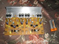
Nice work Vivek.
What device do intend to use for T8?
The trimmer (200R) closest tho the main heatsink bracket is is adjusted to set the bias (idle) current through the output stage. The other (1K0) near the front of the board sets the output offset and should be adjusted so that there is less than 10mV between the output and ground.
Cheers
Q
Thanks quasi. Initially I will be using +/- 35V to do the testing.
I will be using BC546 for T8. As you can see, I have made holes in the 'L' plate to fit it in. Have I made a mistake?
And some more doubts here:
1) How much should the bias current be? And do I set it while measuring the voltage across the 1 ohmr resistors?
2) While setting the output offset, what should be at the input?
3) Also I have used 12K (R7) instead of 10K since I did not have the latter value with me. Is that okay or is 10K an absolute necessity?
Vivek
The hole seems to be too big for the BC546. It should be a snug fit so that good contact is made with the heatsink bracket. If this is now not possible you will be better off mounting it flat against the heatsink bracket and running the leads back through the hole.
1. The bias current shoud be 30mA to 40mA per FET pair. You need to follow the setup procedure described in this thread somewhere that involves replacing the fuses with resistors. I'll try and find it and post it again.
2. Nothing should be connected to the input when setting the offset voltage or the bias current.
3. The 12k resistor is too large for 35 volt rails but it will be ok for rails of 40v or more up to 50v. If you don't have a 10k resistor use an 8k2 or even 6k8.
Cheers
Q
Setup Guide for Nmos series.
I found the set-up guide.
Note: The Nmos200 is limited to 50 volts maximum and suitable only for 8 & 4 ohm loads. For the TO220 version minimum FET spec is Vds = 140v and Pd = 125 watt @ 25° C. Minimum spec for TO247 version is Vds = 140v and Pd = 250 watt.
The setup is done without a load connected to the power amp module. First check your work and make sure output devices are insulated from heatsink.
1. Remove fuses and replace with 100 ohm 5 watt resistors.
2. Make sure power supply polarity is correct and connect amp to power supply and turn on.
3. Check output offset voltage and adjust VR1 to achieve an offset of less than 10 mV.
4. All being well a place a voltmeter across one of the 100 ohm resistors.
5. Adjust VR2 to set the output stage bias current, by measuring the voltage across one of the 100 ohm resistors. Adjust for a reading of 3 volts per output FET pair. I.e; For a 2 FET board set for 3 volts. For a 6 FET board set for a voltage of 9 volts. This equates to a bias current of 30mA per FET pair or 90 mA total. For a 10 FET board set for a voltage of 15 volts.
6. All being well replace the 100 ohm resistors with 10 ohms 1 watt resistors and re-adjust VR2 to get 0.3 volts per FET pair.
7. Once done, remove the resistors and put the fuses in. Re-check the offset voltage and adjust with VR1 if necessary. The amp is ready.
When checking and setting the output offset, fit a shorting plug to the input and leave the output open circuit.
Re-check the offset after connecting the pre-amp/source. If the offset has changed, then investigate.
For first switch on of your transformer I would always recommend using the mains bulb tester wired between the mains and the amplifier. And re-use it EVERY time you modify anything inside the amplifier.
Thanks mate, for the bias setup procedure. I went to the market and bought 10K resistors.
About the BC546, how will I make it stay on the heatsink bracket?
Andrew, I will use a light bulb but does it go between the AC mains and the primary winding of the transformer?
About the BC546, how will I make it stay on the heatsink bracket?
Andrew, I will use a light bulb but does it go between the AC mains and the primary winding of the transformer?
in Post 2466 :
1. Remove fuses and replace with 100 ohm 5 watt resistors.
Should it be 0.5W resistors?
1. Remove fuses and replace with 100 ohm 5 watt resistors.
Should it be 0.5W resistors?
Vivek said:Thanks mate, for the bias setup procedure. I went to the market and bought 10K resistors.
About the BC546, how will I make it stay on the heatsink bracket?
Andrew, I will use a light bulb but does it go between the AC mains and the primary winding of the transformer?
You can use a small clamp made from a metal strip and screw into the heatsink bracket. Or use a BD139 and screw that to the heatsink bracket, but watch for the different pinouts.
The light bulb goes in series with the transformer primary.
bigpanda said:in Post 2466 :
1. Remove fuses and replace with 100 ohm 5 watt resistors.
Should it be 0.5W resistors?
To confirm; use 100 ohm 5 watt resistors.
Cheers
Q
make up a plug top to bulb holder to socket outlet test lead set.Vivek said:Thanks mate, for the bias setup procedure. I went to the market and bought 10K resistors.
About the BC546, how will I make it stay on the heatsink bracket?
Andrew, I will use a light bulb but does it go between the AC mains and the primary winding of the transformer?
The bulb goes in the Live line (NOT across Live to Neutral). Use this plugged in to the wall socket and plug your equipment into the trailing socket.
Select a bulb for first switch on.
A simple transformer with opencircuit secondaries will start on a 40W mains bulb and allow you to check secondary voltages and phasing.
Adding a rectifier & small smoothing bank (<=10mF) should still start on 40W. The flash should reduce to dim within a second or so, the bulb might even go out.
A big smoothing bank will take many seconds to go dim on a small bulb and will not reach final voltage due to the filament dropping some mains voltage (between 10Vac and 50Vac).
For first connection of the power amplifier I would still stay with a 40W bulb. Check that the bias is set to minimum. Change to 60W or 100W bulb and check rail voltages and for any hot/warm components that should be cold. Set your output offset. Start increasing output bias and the bulb will brighten, reset output offset.
Now it is safe to remove the bulb test set and plug your equipment direct to the wall socket, complete the bias setting.
All this has been repeated in many threads!!!!
Hi quasi 

Your construction manual is very explained and nice.
I think it is very helpful for new bees and all diy’rs if you add an extra page in your webpage for Common experienced problems in your popular nmos350 amps, using Practical experience and solutions of all the members who build this amp.
I mean make it like nmos350/500 servicing manual. 😉
In my side I face 4 problems
MJE’s are hot------- put extra heat sink
Out put distortion --------forgot C12
IRFP’s and T4 are blown -------- inter change +/- v voltages accidentally (Mark +v and –v, GND, OUTPUT points on PCB)
-------- Over adjust VR2
I think nmos 350 amps build more than 200 if most of them contribute it will be great First diy amp servicing manual (I think so!)
I think many diy’rs planning this Christmas with their NMOS 350/500 (rock!!!)
cheers
ravi
Quasi
I build bridge power amp using with your NMOS350 2no,
And NE5532 as inverting amp for one channel
The final report is amazing! I bet it can beat many pro amps
Thanks again

I build bridge power amp using with your NMOS350 2no,
And NE5532 as inverting amp for one channel
The final report is amazing! I bet it can beat many pro amps
Thanks again

Hi Quasi,
I don't quite see the point of use 5W resistor. Are they intended to be 'over current' indicators that would blow up when there is something wrong with the pcb (or connection, or whatever) leading to an unexpected high current thru the outputs. If the testing resistor are such high power, which one will blow first, the resistor or the outputs? Please enlightend me for that.
I had blown a few of them before in other projects. If they are low power ones, they will just 'pop' and blast open with a big 'bang' leaving burnt marks on the fuse holders, but if they are hight power, I am wondering what might happen during the blast.
bigpanda said:Hi Quasi,
I don't quite see the point of use 5W resistor. Are they intended to be 'over current' indicators that would blow up when there is something wrong with the pcb (or connection, or whatever) leading to an unexpected high current thru the outputs. If the testing resistor are such high power, which one will blow first, the resistor or the outputs? Please enlightend me for that.
I had blown a few of them before in other projects. If they are low power ones, they will just 'pop' and blast open with a big 'bang' leaving burnt marks on the fuse holders, but if they are hight power, I am wondering what might happen during the blast.
100 ohm resistors will limit the current to the output stage to under 1 amp and hopefully preserve it under fault consitions. For example if the rails are 70 volts the maximimum current that can flow is 700mA and this equates to a power dissipation of 49 watts. If your multimeter (using the 20 volt scale) is connected across the resistor goes over-scale when you turn on, you have enough time to turn it off and hopefully save the 5 watt resistor.
If the 5 watt resistor does die it will gracefully go open circuit without much fuss or damage.
Cheers
May I ask as to what is the dissipation in the Vas Transistor and its associate CCS. I notice that they run quite hot with good heatsinking but without any problems. The reason I am asking is to try a different transistor for Vas with higher Ft and lower Cob; there are good transistors with Ic of 100mA to 300mA, Hfe bias varying between 10mA and 50mA and Cob less than 5pf.
None of the desirable transistors seem to be as rugged as the MJE340/350 pair but it is just the itch to try something different.
Thanks.
None of the desirable transistors seem to be as rugged as the MJE340/350 pair but it is just the itch to try something different.
Thanks.
Samuel Jayaraj said:May I ask as to what is the dissipation in the Vas Transistor and its associate CCS. I notice that they run quite hot with good heatsinking but without any problems. The reason I am asking is to try a different transistor for Vas with higher Ft and lower Cob; there are good transistors with Ic of 100mA to 300mA, Hfe bias varying between 10mA and 50mA and Cob less than 5pf.
None of the desirable transistors seem to be as rugged as the MJE340/350 pair but it is just the itch to try something different.
Thanks.
The total dissipation of the second stage transistors is almost the current flowing through them of 12.5mA x the voltage rails differential. Ie. if you had rails of 50v then the dissipation is almost 100v x 12.5mA = 1.25 watts. Some of this power is dissipated by the associated resistors but not much.
You could use a better transistor here in terms of gain and speed etc. but probably not in the third stage.
Cheers
Q
Quasi, thanks a lot. That was a reply quicker than I expected.
This is good news since there are a lot of transistors with better characteristics to be used in this position and they all have a Pd in the region of 7Watts to 10Watts. This should suffice.
How they sound only trying them out will tell. I have already got very, very good sound from the KSE340/350 combination in the Vas/CCS positions.
- Home
- Amplifiers
- Solid State
- Power amp under development