Plot twist: after testing bias sensor performance during heating, this morning I also tested cooling. I should have set it to record that during the previous tests, but I forgot, so here we go again...
If the thermal sensor has delay during heating, then the output stage will overbias. If it has delay during cooling, and the thermal sensor ends up hotter than the transistors, then it will lower the bias too much and the output stage will underbias, which should absolutely be avoided.
First is the sensor attached to the collector leg of MJL3281. It works very well during heating, but not at all during cooling. The MJL3281 silicon is cooled very quickly by the heat sink, but the collector leg stays quite warm for a long time.

Next is BD139 on top of MJL3281 under the metal bar. It has the same problem, it remains hot while MJL3281 cools down.

I'm out of 0805 SMD red leds, so I tried a 1206: it doesn't work that well as a temperature sensor.
This is a MMBT3904 on the copper slug on which 2SC5706 is mounted. It tracks the cooldown very well.

I should have thought about that before: if the thermal interface is good, which it should, the power transistor will cool down to the temperature of its heat sink very quickly. So the bias sensor should be between heat sink and transistor to avoid lag during cooldown. The only practical solution to do this is to mount both the transistor and the sensor on the same copper slug.
Therefore:
Doing an output stage with large transistors, no emitter resistors at all, and no special snowflake autobias circuit looks pretty much impossible due to not being able to track the temperature.
If thermaltrak diodes are mounted on the leadframe by the side of the transistor, they could work for that, but a lot of people say bad things about them. If they are mounted too far from the transistor itself, the same thing will happen as above with the LED: they won't cool down fast enough, resulting in underbias.
On the other hand, a resistor-free output stage is possible with SMD transistors (with cascode) but since you can't parallel them without emitter resistors, it will be either low power, or way too many parts.
If the thermal sensor has delay during heating, then the output stage will overbias. If it has delay during cooling, and the thermal sensor ends up hotter than the transistors, then it will lower the bias too much and the output stage will underbias, which should absolutely be avoided.
First is the sensor attached to the collector leg of MJL3281. It works very well during heating, but not at all during cooling. The MJL3281 silicon is cooled very quickly by the heat sink, but the collector leg stays quite warm for a long time.
Next is BD139 on top of MJL3281 under the metal bar. It has the same problem, it remains hot while MJL3281 cools down.
I'm out of 0805 SMD red leds, so I tried a 1206: it doesn't work that well as a temperature sensor.
This is a MMBT3904 on the copper slug on which 2SC5706 is mounted. It tracks the cooldown very well.
I should have thought about that before: if the thermal interface is good, which it should, the power transistor will cool down to the temperature of its heat sink very quickly. So the bias sensor should be between heat sink and transistor to avoid lag during cooldown. The only practical solution to do this is to mount both the transistor and the sensor on the same copper slug.
Therefore:
Doing an output stage with large transistors, no emitter resistors at all, and no special snowflake autobias circuit looks pretty much impossible due to not being able to track the temperature.
If thermaltrak diodes are mounted on the leadframe by the side of the transistor, they could work for that, but a lot of people say bad things about them. If they are mounted too far from the transistor itself, the same thing will happen as above with the LED: they won't cool down fast enough, resulting in underbias.
On the other hand, a resistor-free output stage is possible with SMD transistors (with cascode) but since you can't parallel them without emitter resistors, it will be either low power, or way too many parts.
Emitter resistors shunted by Schottky diodes (like RCA).
Is there a circuit where that doesn't screw up gm flatness?
Would it be possible to connect the BD139 to the metal plate with the screw hole (not sure what it's called) on the MJL3281 to get better cooldown tracking? I guess your top bar pressing on the BD139 also stores heat and delays the cool down of sensing transistor.
I had pretty good results modifying a Proton amp without emitter resistors (original design) by placing the sensing transistor on top of the output transistor using the same screw. For sure it could be improved, but bias & distortion performance was improved a lot compared to standard with the sensing transistor on the heat sink. I could bias it slightly higher since the tracking was better, to keep it above 'critical' bias limit at all times.
I had pretty good results modifying a Proton amp without emitter resistors (original design) by placing the sensing transistor on top of the output transistor using the same screw. For sure it could be improved, but bias & distortion performance was improved a lot compared to standard with the sensing transistor on the heat sink. I could bias it slightly higher since the tracking was better, to keep it above 'critical' bias limit at all times.
Or you can use 'thermal glue' instead of metal screw:
https://www.amazon.com/gp/product/B07HCDRL7W/ref=ppx_yo_dt_b_search_asin_title?ie=UTF8&psc=1
https://www.amazon.com/gp/product/B07HCDRL7W/ref=ppx_yo_dt_b_search_asin_title?ie=UTF8&psc=1
Would it be possible to connect the BD139 to the metal plate with the screw hole (not sure what it's called) on the MJL3281
Not sure what you mean...
But I could try a small sensor inside the screw hole, since I'm not using it. Could be a nice way to get the temperature of the heat sink right under the transistor... but it is not close to the semiconductor itself. There is also the option of drilling through the heat sink and putting a thermocouple under the transistor die... I have a thermocouple in the reflow oven and heat sinks with holes in them, but no thermocouple IC... well, I have good instrumentation amps with a lot of gain so why not.
> I guess your top bar pressing on the BD139 also stores heat and delays the cool down of sensing transistor.
It's probably helping it cool down by acting as a heat sink: temperature rise of BD139 was only about half of MJL3281. So in a Vbe multiplier it would cancel half the Vbe change. Still much better than on the heatsink.
I could try putting a rubber washer between the two, I have some pretty hard ones, that'll probably work..
Mounting it on a copper slug would definitely work as it did for the 2SC5706, but it would need a pretty big chunk of copper.
I had pretty good results modifying a Proton amp without emitter resistors (original design) by placing the sensing transistor on top of the output transistor using the same screw. For sure it could be improved, but bias & distortion performance was improved a lot compared to standard with the sensing transistor on the heat sink. I could bias it slightly higher since the tracking was better, to keep it above 'critical' bias limit at all times.
Well, even if does underbias after a loud passage, if the mod allowed you to increase the bias and the effects cancel, that would count as an upgrade!
If this amp is stable without emitter resistors that gives me hope. What was the bias, and what is the Vce of the transistors?
OK, so todolist for tomorrow:
Stuff mentioned above.
Measure thermal resistance with the transistor fastened with the big metal bar, and then with just the screw. I think I have a heatsink with M3 tapped holes somewhere.
And then I'm going make a real Vbe multiplier, and use the switching MOSFETs on the setup to make a square wave from V+ to V-, connect a 8R load resistor between that and the output, and use the square wave to heat both transistors. There will be a pause every time it switches, it will stay at zero output current for long enough to measure the bias. Then it will turn the FETs off and measure the bias as it settles. That will show the Vbe multiplier in action.
Other suggestions?
Last edited:

Something like class AC, by J. Broskie: CCDA & Class-ACIs there a circuit where that doesn't screw up gm flatness?
I think I have posted something about it on this forum.
It does work, but it is expensive regarding power dissipation.
Member Kenpeter has also posted some interested ideas with schottky's, but unfortunately he doesn't seem to be active anymore. I just hope he is safe and well
BV> This is good stuff, but he does no simulations of cooldown...
Another option if i decide to use the cascode output stage: when Vce is constant, dissipation is proportional to current, which is easy to measure. So the junction temperature can be calculated with basically an opamp and a RC network, or a couple BJTs, which is not complicated. This gives an instant result.
My current goal is to make a reasonably stable output stage without any emitter resistors and then measure it both for crossover spikes and distortion to see if this is worth pursuing (spice does model distortion correctly for BJTs but I have doubts about the crossover spikes). To do this, the sensor transistor on top of the package will be absolutely fine, because there will be no cooldown and the test can run at 10V Vce, so bias should be stable.
Comparison with the MOSFETs will then decide where this project goes...
Last edited:
Something like class AC, by J. Broskie: CCDA & Class-AC
I think I have posted something about it on this forum.
It does work, but it is expensive regarding power dissipation.
Member Kenpeter has also posted some interested ideas with schottky's, but unfortunately he doesn't seem to be active anymore. I just hope he is safe and well
I remember seeing this schematic before...
He's using more than 1A bias and that's way more than I want. Using this schematic with more realistic bias gives a gm curve with more bumps depending on the offset voltage between the transistors. If the bumps are exactly in the right place to cancel out, why not, but they will move with temperature...
Here Class AB+C: Anybody tried it? Is it worth it?
Class-AB+C is the same thing as Bob Cordell's DoubleCrossTM and is explained in his 2nd Ed. book CordellAudio.com - Home Chapter 13, Section 7 and 8.
Running a pair like this at a higher idle current reduces the temperature variations in the power transistors with typical music power swings. It stops gm doubling. But there is still the warm up time before bias settles.
Combining Class-ABC (DoubleCross) with Auto Bias locks bias so you get lowest possible distortion from turn-on, no matter what the music brings.
Not sure what you mean...
The piece of metal with he mounting hole on the power transistor, try to thermally connect the sensing element to it. I have no better way to describe it 🙂
Maybe solder a small piece of copper between power transistor and sensing element, a big piece of copper should not be needed just to transfer the heat to the sensor, but i do believe the best should be to connect it to the metal on the power transistor.
Well, even if does underbias after a loud passage, if the mod allowed you to increase the bias and the effects cancel, that would count as an upgrade!
Yes, it was easy to replicate with distortion measurements. I ran high power bursts, and measured the distortion (and Iq) at a lower level while it cooled down. Basically just ARTA and FFT and playing around with the volume control.
It was in these shorter heat transients that the improvement was most significant, the slow heating of the heat sink was pretty well compensated with the sensing transistor on the heat sink.
Iq did still vary a little with the transients, so I had to overbias slightly.
If this amp is stable without emitter resistors that gives me hope. What was the bias, and what is the Vce of the transistors?
I don't have the amp any more, and memory is short.. I think I set Iq around 40-50mA, I wrote it on the inside of the amp, but no other place..
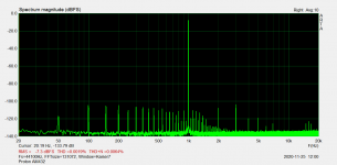
I attached a schematic of the amp from the internet. I think Proton made several amps without emitter resistors. I did burn some transistors before I got it where I wanted it though.. If you make one without emitter resistors, remember to make a jumper or similar on the PCB to measure Iq. 🙂
EDIT:I found a dist measurement of it too, so I added that. I think it's 1W 8ohm.
Attachments
Last edited:
BV> This is good stuff, but he does no simulations of cooldown...
If you look at this as multiple R-C circuits with more time constants, it work in both directions. Teperature rise and fall, only inverse reaction.
Overbias or underbias after transients, it is only about gain in thermal compensation circuit, if time constats are correct. Critical is fast tracking of thermal changes.
Last edited:
I remember seeing this schematic before...
He's using more than 1A bias and that's way more than I want. Using this schematic with more realistic bias gives a gm curve with more bumps depending on the offset voltage between the transistors. If the bumps are exactly in the right place to cancel out, why not, but they will move with temperature...
The lighter version I proposed used a pair of schottky's instead of transistors, and could work at a lower Iq:
Class AB+C: Anybody tried it? Is it worth it?
In the meantime, I have also found a creative use of schottky by Kenpeter:
Diodes instead of or across emitter resistors
I investigated the mounting technique.
MJL3281 pressed on heat sink by square aluminium hollow tube.
versus
MJL3281 mounted on heatsink with M3 screw and washer (torqued as hard as I can with screwdriver).
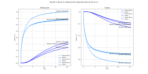
In both cases, Keratherm 86/82 is used as interface material. The two heat sinks are different: one has M3 holes for the screw, the other has holes that fit the bar. So, just to look at the left part of the graph, where the heat sink doesn't have time to act, it's only between the device, the silpad, and the thermal mass of aluminium behind it.
What the curve shows is transient thermal impedance, or how much the device heats with 1W power with time. The leftmost bit where it quickly rises is the thermal mass of the chip and leadframe, then it stabilizes to the thermal resistance junction to heat sink, then it slowly rises as the heat sink heats up. So the interesting part is right after the first bend, that's where the thermal resistance of the silpad and mounting technique shows up.
Conclusions:
- With the screw no significant difference between washer and no washer.
- The bar gives 0.1°C/W less thermal resistance than the screw, a gain of about 15%
- The heat sink with the bar is thicker, which is visible in the slope of the curve.
Since thermal resistance is important not just against overheating, but against bias instability too, I will keep the bar.
MJL3281 pressed on heat sink by square aluminium hollow tube.
versus
MJL3281 mounted on heatsink with M3 screw and washer (torqued as hard as I can with screwdriver).
In both cases, Keratherm 86/82 is used as interface material. The two heat sinks are different: one has M3 holes for the screw, the other has holes that fit the bar. So, just to look at the left part of the graph, where the heat sink doesn't have time to act, it's only between the device, the silpad, and the thermal mass of aluminium behind it.
What the curve shows is transient thermal impedance, or how much the device heats with 1W power with time. The leftmost bit where it quickly rises is the thermal mass of the chip and leadframe, then it stabilizes to the thermal resistance junction to heat sink, then it slowly rises as the heat sink heats up. So the interesting part is right after the first bend, that's where the thermal resistance of the silpad and mounting technique shows up.
Conclusions:
- With the screw no significant difference between washer and no washer.
- The bar gives 0.1°C/W less thermal resistance than the screw, a gain of about 15%
- The heat sink with the bar is thicker, which is visible in the slope of the curve.
Since thermal resistance is important not just against overheating, but against bias instability too, I will keep the bar.
Attachments

Hi peufeu,
Yes, heat sink effectiveness has a lot to do with bias stability that I have seen in practice over many decades. Your findings are no surprise. For your experiments you really need to use the same type of heat sink or you can't compare results.
There is an optimum torque for transistor case type laid out in an application note first put out by Motorola, and kept in On Semi's collection. It isn't nearly as high as you might think. "Cranking" the parts down may crack the die inside, or distort the heat sink so you don't have optimum contact, or simply strip the holes.
-Chris
Hi peufeu,
Yes, heat sink effectiveness has a lot to do with bias stability that I have seen in practice over many decades. Your findings are no surprise. For your experiments you really need to use the same type of heat sink or you can't compare results.
+1
I'm using the small allen wrench to make sure I don't go overboard with the torque...
I will try to compare the screw and the bar using another method: same heat sink, but the "screw" will actually be the bar, but I will place it over the screw hole instead of placing it over the die.
Meanwhile, request from Rallyfinnen:
I mounted the BD139 on top of the MJL3281 and did 2 tests in 2 slightly different positions. The result is that where it is placed matters a lot: without x-ray vision it is very difficult to know where to put it. Both places looked "over the die" to me.
Then I inserted a cardboard shim between the BD139 and the metal bar, to act as an insulator. It didn't result in a significant change. So the cooling or thermal mass effect from the bar is smaller than the effect of positioning the sense transistor exactly in the right spot.
EDIT: In fact thermal resistance of the MJL also changed a lot, I must have torqued it differently, or the BD139 as it moved changed where the pressure is applied... so that's pretty inconclusive.
Attachments
Last edited:
OK, all these bias sensor tests are not helping towards the current goal which is to know if there is a point in making an output stage without emitter resistors.
The tests involved do not require correct bias during cooldown, but they do require correct bias during the test, otherwise I'll have no idea what bias I'm testing at, which means fair comparison with MOSFETs will not be possible.
For this I can simply use MMBT3904 soldered on the collector lead as a temperature sensor. So that's what I will do.
- Home
- Amplifiers
- Solid State
- Power amp OUTPUT STAGE measurements shootout