Hi, I am in the process of building my NuClassD I purchased from Pete on fleabay.
Using the recommended power supply I am getting 29.5 VDC output to the signal boards, and cannot get the bias to drop below 15v, well away from the spec'd 13v across the test points.
I have not tried to adjust the gain, the 1meg pots are set at about their midpoint, 500k.
Thanks for any input anyone has.
Regards,
Matt
15V is fine. The bias point will be affected some by the gain pot as well.
You can change R4 from 100k to 120k or 150k if you want to bias it lower and get more adjustment range, if you want to try tweaking it for more or less distortion.
Pete
You can change R4 from 100k to 120k or 150k if you want to bias it lower and get more adjustment range, if you want to try tweaking it for more or less distortion.
Pete
Thanks, Pete!
I may leave it as is...
Hi Matt,
I had similar results with the same responsive reply from Pete.
I left it as is.....🙂
It's working nicely
The amp is functioning nicely, i am quite happy with the sound!
I have a rather pronounced tube harmonic on the left channel when i turn the amp on or off, or give the chassis a rap, but it does not appear to happen with music playing. It is the typical 5k or so harmonic with a slow decay over about 20 seconds, as described by others using the tubes in projects.
I have the tubes mounted on the boards with the supplied foam tape, but will look at other additional damping measures to see if they help.
Received the PCBs and Nutube 6P1s in the UK today, and this shipment only took 7 days! Maybe I'm lucky, probably not all shipments arrive so quickly.
Anyway the boards look great. I'm building them as mono-blocks to sit right behind my speakers, using Lundahl transformers to accept a balanced inputs. Now waiting for enclosures from China.
Has anyone thought about the longevity of the 6P1? It's quoted as 30K hours - about 3.4 years, so not something to be left permanently powered unless the Nutube was socketed.
NuClassD Amp Build Notes
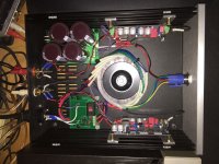
Here's my build for a NuClassD stereo amp with common power supply. All parts used for the PCB ended up being stock per Pete's BOM except the Korg plate resistor values (more on that later). I also used his power supply PCB and BOM.
This is not a project for newbees. It is perhaps the most difficult PCB I have ever stuffed and soldered. It has a very tight layout. An extra fine tip iron and small diameter solder is recommended, along with a magnifier for construction and inspection. Also, a lot of patience and minimal coffee for a steady hand.
A few spots (mostly at ground plane locations) have what appears at first to be funky thru hole plating but all solder joints turned out functionally OK. When I first fed a 1K sine wave into a board and put my dual trace scope on both the input and output to have a look at the waveform and look for the unwanted, I was greeted by a flashing fault LED. There was that sinking feeling until I had the “oh, duh!” moment when I realized the scope probe negative clip was grounding the negative side of the loudspeaker output, a total no-no for a bridged amp design. But nice to know the protection circuit works. I ended up checking for DC on the outputs with my Fluke meter and found around 10 – 15 mV, terminals unloaded, a very reasonable value.
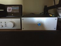
The chassis is a diyAudio store Galaxy 2U 230X280 w/ 10mm front panel. The integral LED ring front panel power switch is an API-ELE 19mm Latching Push Button Switch purchased from Amazon. It's essentially a Bulgin knockoff for under $10. I used a 10K external current limiting resistor in addition to the internal 12V one for setting the LED brightness. I used a different IEC unswitched fused power socket that I had on the shelf and mounted the IEC PCB separately on standoffs.
This is not an inexpensive project for a 50 w/ch class D amplifier. Total parts cost was about $400. My leap of faith was based on a positive outcome from building Pete's NuTube Buffer preamp. On first listen to this amp I was a bit dismayed, but only a bit, because I had found it impossible to run the Korg plate voltages at less than 14.2 VDC. Pete's schematic showed 13 VDC. A quick email to Pete and an equally quick response came with a recommendation to change the plate resistors to 150K, perhaps as high as 200K, since I said I was looking for more second order harmonic. I settled on 160K and 11.75 VDC on the plates. Channel gain was set using a 0.1V 1kHz sine wave input, starting with one channel at the multi-turn pot mid-point (nominally 1 meg total of NFB resistance), measuring the output voltage on that channel and then adjusting the other channel's output to match.
How does it sound? I've been listening at my desk on a pair of mid-1980's ADS 6” 2-way bookshelf speakers. Preamp is an even older harman/kardon hk 725 discreet FET design. The ADS had previously always sounded a bit soft and tubby in the bottom end. Not any more. Nice tight bass, plenty of power. That clarity and control extends across the entire bandwidth. This is a very revealing amplifier with a bit of triode excitement thrown in. I am preferring the h/k preamp set at -2 dB in the treble (10kHz knee) on most source material.
My next step is to connect it to my REW distortion analysis setup running on my PC and see what is going on with the balance between second and third order harmonic content. I may yet play around some more with the plate loading on the Korg tube. So far, the more I listen to this amp, the more I like it, which is a good sign. In the past, I've easily spent $400 building FirstWatt Class A clones from the diyAudio store. This amp holds it's own against them in overall quality but is a very different beast. If you are up for a build challenge, this might just be your amp.
Here's my build for a NuClassD stereo amp with common power supply. All parts used for the PCB ended up being stock per Pete's BOM except the Korg plate resistor values (more on that later). I also used his power supply PCB and BOM.
This is not a project for newbees. It is perhaps the most difficult PCB I have ever stuffed and soldered. It has a very tight layout. An extra fine tip iron and small diameter solder is recommended, along with a magnifier for construction and inspection. Also, a lot of patience and minimal coffee for a steady hand.
A few spots (mostly at ground plane locations) have what appears at first to be funky thru hole plating but all solder joints turned out functionally OK. When I first fed a 1K sine wave into a board and put my dual trace scope on both the input and output to have a look at the waveform and look for the unwanted, I was greeted by a flashing fault LED. There was that sinking feeling until I had the “oh, duh!” moment when I realized the scope probe negative clip was grounding the negative side of the loudspeaker output, a total no-no for a bridged amp design. But nice to know the protection circuit works. I ended up checking for DC on the outputs with my Fluke meter and found around 10 – 15 mV, terminals unloaded, a very reasonable value.
The chassis is a diyAudio store Galaxy 2U 230X280 w/ 10mm front panel. The integral LED ring front panel power switch is an API-ELE 19mm Latching Push Button Switch purchased from Amazon. It's essentially a Bulgin knockoff for under $10. I used a 10K external current limiting resistor in addition to the internal 12V one for setting the LED brightness. I used a different IEC unswitched fused power socket that I had on the shelf and mounted the IEC PCB separately on standoffs.
This is not an inexpensive project for a 50 w/ch class D amplifier. Total parts cost was about $400. My leap of faith was based on a positive outcome from building Pete's NuTube Buffer preamp. On first listen to this amp I was a bit dismayed, but only a bit, because I had found it impossible to run the Korg plate voltages at less than 14.2 VDC. Pete's schematic showed 13 VDC. A quick email to Pete and an equally quick response came with a recommendation to change the plate resistors to 150K, perhaps as high as 200K, since I said I was looking for more second order harmonic. I settled on 160K and 11.75 VDC on the plates. Channel gain was set using a 0.1V 1kHz sine wave input, starting with one channel at the multi-turn pot mid-point (nominally 1 meg total of NFB resistance), measuring the output voltage on that channel and then adjusting the other channel's output to match.
How does it sound? I've been listening at my desk on a pair of mid-1980's ADS 6” 2-way bookshelf speakers. Preamp is an even older harman/kardon hk 725 discreet FET design. The ADS had previously always sounded a bit soft and tubby in the bottom end. Not any more. Nice tight bass, plenty of power. That clarity and control extends across the entire bandwidth. This is a very revealing amplifier with a bit of triode excitement thrown in. I am preferring the h/k preamp set at -2 dB in the treble (10kHz knee) on most source material.
My next step is to connect it to my REW distortion analysis setup running on my PC and see what is going on with the balance between second and third order harmonic content. I may yet play around some more with the plate loading on the Korg tube. So far, the more I listen to this amp, the more I like it, which is a good sign. In the past, I've easily spent $400 building FirstWatt Class A clones from the diyAudio store. This amp holds it's own against them in overall quality but is a very different beast. If you are up for a build challenge, this might just be your amp.
Attachments

Thanks, Pete!
I may leave it as is...but I appreciate your response!
Matt
RE: plate voltages. I find I like the sound of the NuTube with more of a 2nd harmonic signature. For example, in comparing two circuits with very similar topology, the Millett NuTube Buffer and the Pass B1 Korg preamp, Pete runs his tube with 475K plate resistors at 11.5 VDC which is a pretty low distortion setting, both 2nd and 3rd. Nelson runs his tube with 332K plate resistors at 9.5 VDC which yields 1.5% 2nd harmonic at 1.0V output with very little 3rd harmonic. I found I like 332K and 9.7 VDC which is a tad less 2nd order than the Pass setup.
I found when I loaded the 332K resistors into Pete's Buffer PCB and set the tube plates to 9.7 V, the sonic signature of the circuit was virtually identical to Nelson's B1 Korg. I did add 1K grid stoppers to the mosfet inputs on the Buffer. These are highly recommended.
I'm not sure how the parallel plates and higher supply voltage (29.5 vs 24 VDC) of the NuClassD circuit correlates to its plate resistor values and plate voltage settings to obtain a similar sonic signature. I do know that so far I like 160K and 11.75 VDC better than 100K at the 14.2 VDC which was as low as my build would go in stock config. I'll be running some distortion measurements to see how to get closer to my target and whether I actually like that much 2nd order in the NuClassD.
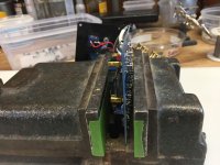
In the mean time, changing R4 on the NuClassD PCB can be daunting due to the tight spaces and thru-hole plating, so I thought I'd share how I do it relatively painlessly:
First, you need some way of holding the PCB vertically on edge. If you are right handed, with the component side to the left and the bottom side to the right. I use an old smooth jawed drill press vise with the jaws taped and barely closed enough to keep the board stable. Some blocks of wood screwed or clamped to a board or something else could also work.
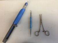
You also need a serrated jaw locking hemostat, a solder vac tool and a very slender tapered pick or needle with a point smaller than a PCB trace hole tapering smoothly up to something larger than the hole.
Start by marking the bottom of the PCB with a fine point sharpie. I draw a line between the two pads I am about to desolder. This makes relocating the pads easy and helps reduce mistakes. Clamp the tip of the hemostat on the component side to one leg of R4 and hold the tool in a way that allows some extended spare fingers to apply pressure to the component side of the board. Apply the soldering iron tip to the pad on the bottom and the resistor leg should pull right out fairly easily. Repeat with the other leg.
Now apply the solder vac perpendicular and tight to the component side of a hole, the iron to the other and suck out the leftover solder. Take a look against the light to make sure the hole is completely clear. Finally, use the pick or needle on each side of the hole to gently burnish away any micro roughness.
I'll post my final resistor value and plate voltage after I do some more analysis and listening.
Attachments
The amp is functioning nicely, i am quite happy with the sound!
I have a rather pronounced tube harmonic on the left channel when i turn the amp on or off, or give the chassis a rap, but it does not appear to happen with music playing. It is the typical 5k or so harmonic with a slow decay over about 20 seconds, as described by others using the tubes in projects.
I have the tubes mounted on the boards with the supplied foam tape, but will look at other additional damping measures to see if they help.
FYI, there is extensive discussion on Korg tube mounting scattered throughout the Pass B1 Korg forum:
B1 with Korg Triode
It's up to 265 pages now so you will have to do some searching.
Hi avdesignguru,
Thanks for posting your impressions after experimenting with R4. My plate voltage would not adjust below 14vdc also. I will have to re-visit my NuClassD and increase R4 similar to you. It’s a very tight and densely populated board as you pointed out, I will back off the espresso as per your recommendation 😀
Thanks for posting your impressions after experimenting with R4. My plate voltage would not adjust below 14vdc also. I will have to re-visit my NuClassD and increase R4 similar to you. It’s a very tight and densely populated board as you pointed out, I will back off the espresso as per your recommendation 😀
Nice removal technique, Thanks!
It’s a nice amp to have on these hot summer days, it barely get warm.
Happy 4th!!
It’s a nice amp to have on these hot summer days, it barely get warm.
Happy 4th!!
NuClassD Amplifier Setup
Thought I would share this on the forum:
I found noticeable differences in the sound character of this amplifier based on the gain settings trim pot. Experimentation was simple. I just used a 1KHz signal from a free app on a smart phone, measured the input voltage and then the output voltage (unloaded). I then divided the output reading by the input reading to determine straight voltage gain (not in dB).
I found that once I brought the output voltage gain down to 36 times the input, the bass got cleaner and the overall sound character of the amplifier improved. I used 0.052V in for 1.872V out and set both channels the same. Pretty low source input level but I had been measuring things in REW prior which needed lower voltage input so I just left it at 0.052V. The resulting sound was a noticeable improvement over the higher gain setting of closer to 40 that was more or less at the mid-point of the trim pot. I went from 40x > 38x > 36x and could hear the difference each time. I arbitrarily stopped at 36x because I wanted the least amount of NFB that gave me the sound I was looking for.
I measured the harmonic content using Room EQ Wizard running on a PC with an Eiderol USB interface. I used a line level isolation transformer good for at least +20 dBV to prevent grounding the amplifier output. I had pre-set the plate voltage at 13 volts, Pete's recommended setting. I had to use 160K plate resistors to get it to go that low. This gave me a 2nd harmonic signature of about 4X the 3rd harmonic level. I find absolute values in REW pretty useless since the distortion levels change so much with the signal level through the NuTube. I made my measurements with input from the USB interface attenuated to -6dB at the app. I did not use a voltage divider on the loudspeaker output. There may have been some additional H2 distortion from the transformer but at 1.872V probably not too much.
So far I like the 13V plate setting for the amount of H2 I'm getting. I may try dropping it a bit lower after I get used to the sound of this amp with the new gain setting.
On a side note, before this, I was experiencing some 4K - 5K ringing that developed intermittently. Pete helped me identify it as the NuTube filament ringing. Curiously enough, now that the gain setting is lower I'm not getting the tube ringing anymore. Not sure if is because the bass is cleaner or something to do with the additional NFB at the tube input or both. At least I know I will need to do some extra tube damping if it reoccurs.
NuClassD Amp polarity
One more note: the NuClassD amplifier circuit inverts absolute signal polarity. I like the way the amp sounds better with the loudspeaker wiring reversed to correct the polarity. It's an easy experiment and I recommend giving it a try to see what you think.
One more note: the NuClassD amplifier circuit inverts absolute signal polarity. I like the way the amp sounds better with the loudspeaker wiring reversed to correct the polarity. It's an easy experiment and I recommend giving it a try to see what you think.
Hello,
a quick question, I am quite unexperienced with tubes. Can the amplifier be used with a potentiometer right before the input (as a passive pre)? I would like to use a 10k log pot between the NuclassD and an Allo Boss DAC and get away without extra input buffer. Can the input voltage divider (100k and 100k) be modified to higher values without messing with the tube working points?
Thank you for brief feedback...
Florian
Hello,
a quick question, I am quite unexperienced with tubes. Can the amplifier be used with a potentiometer right before the input (as a passive pre)? I would like to use a 10k log pot between the NuclassD and an Allo Boss DAC and get away without extra input buffer. Can the input voltage divider (100k and 100k) be modified to higher values without messing with the tube working points?
Thank you for brief feedback...
Florian
NuClassD circuit already has JFET buffers ahead of the NuTube. JFETs have a very high input impedance (1 meg?), in this case, limited to 100K by R3. Higher than 100K and you may start to pick up noise and/or RF.
10K pot would set the impedance the Allo Boss sees.
Avdesignguru, get some free fft view in software and look at spectra with gain change.
As mentioned in post #34, I'm already using REW FFT analysis and looking at relative H2 and H3. I was referring to absolute measured values changing with signal level.
- Home
- Amplifiers
- Tubes / Valves
- Posted "NuClassD" amp design: 50W hybrid class-D / Korg Nutube