George what cap voltages are you using. I have been trying to find some in higher voltages but it seems that 450volts is the max that is readily available.
The largest voltage electrolytic that I have found that physically fits in the board is 500 volts. Panasonic makes some 500 volt caps that will work, and so does CDE. I found some good deals on CDE parts that I mentioned very early in this thread but they are gone now. However, I do not have any of these in my board.
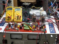
I got my board to experiment with. That is why I built it with all of the parts on the same side of the baord as the tubes. That way I don't have to flip it over to probe it or change parts. As with all of my amplifier designs, especially ones with no pre-defined goals, I use external power supplies. I have used this board with tiny tubes at 250 volts and I have turned up to 600+ volts causing a capacitor explosion. Since all of the supplies are external, I don't need all of the large electrolytics on the board. C1, C2, C3, C6, C22, and C30 are not installed in my board. Each supply has a bypass cap on the board to trap any noise that may be on the supplies. I have 200 volt electrolytics on the negative bias supply (C8, C16, C11, C12, C13 and C14). I have needed close to -100 volts to control some sweep tubes at big B+ voltages. I put 450 volt caps on the screen supplies (C4, C5, C21, C23 and C26) In case I found the need to crank up the screen voltage. I have found that 150 to 200 volts works best with sweep tubes. Some of the other odball tubes that I have tried did like more voltage, so the 450 volt caps were a good idea.
When I started down this road the biggest power supply that I had went to 550 volts, maybe a little less when the current meter is buried. I knew that I wasn't going to run this thing at 335 volts, so I installed slightly larger (39K)plate load resistors (R50, R51, R53, and R55), and raised the decoupling resistors (R48 and R49) to 10K 2 watt. C24 and C27 were 47 uF 450 Volt Nichicons. All was well with the 550 volt supply, but the voltage across the caps was about 470 volts with the power supply cranked all the way up. When I got the 650 volt supply it didn't take long for one of these capacitors to violently explode. They are still 450 volt caps since 450 volts is too much voltage for the tiny driver tubes that I am now using (6GU5). The resistors are now 22K 3 watt, and I will put resistors across the caps as needed to lower the voltage. I will probably stick 500 V caps there just in case. I will likely use 2 X 10 K 3 watt resistors in series too for voltage capability. This should insure that the board is good to what ever voltage I see fit to feed it.
In my initial build I had a 1.6 uF 600 volt ASC film cap across the B+ (C25). Several years ago I blew some film caps up with a defribilator in a controlled experiment, and I know that a film cap of that size could blow the board in half! This, even I didn't want to see, so now there are two .22 uF 1.6 KV Vishay MKP's in parallel there now.
If I actually do get a three day weekend in a few days, I plan to dial this thing up to the end of the power supply with the 35LR6's.
OK, I have a big bunch of NOS Sylvania 35LR6's and a fair collection of 6 volt sweep tubes. Ideally I would like to run both in the same board, but how? I was thinking about cutting the traces between the driver and output tubes and running two seperate heater circuits.
I noticed something rather strange and undocumented about my 35LR6 tubes. In both of my books pin 7 is labled "IC" internal connection. on the Sylvania 6LR6's that I have pin 7 goes nowhere. On the Sylvania 35LR6's pin 7 is a heater center tap. The plate structures of the two tubes are completely different too. The 6LR6's have large heat radiating fins added to the plates that are not present on the 35LR6's.
So, given this discovery I have found a rather unorthodox way to run both tubes in the same board using stuff I already have on my bench. It is even possible to mix the 6 volt tubes and 35 volt tubes in the same board. How?
Run a wire connecting all of the pin 7's on the output tubes together. Connect the board to the 6.3 volt AC heater supply in the usual manner. 6 voilt tubes should still light as will the driver tubes since nothing has chaanged. Apply 17.5 volts DC between one side of the 6.3 volt supply and the wire connecting the pin 7's together. Now the 6 volt tubes are unaffected since pin 7 is not connected to anything. Verify this on tubes other than 'LR6's. On the 35 volt tubes we have 17.5 volts DC on one half of the heater and 17.5 volts of DC with 6.3 volts of superimposed AC on the other half. The average on this half is still 17.5 volts. Yes, I tried it, and yes it works. No, I haven't flipped the power switch on the main B+ yet.
This leaves out the 36KD6 since it does not have a tapped heater. Some other brands of 35LR6's may not either, but I don't have any. I only have one toasty looking 36KD6, so that isn't a big deal either.
Newb question
I am just finishing up my amp and am adding a PEC pot for passive volume control. Upon checking the resistances of the pot I notice a consistent 2.5K difference between channels. Do I add a resistor of like value to the higher channel? And if so what type would be recommended? Thanks in advance.
Paul
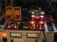
I have had this big box full of NOS 35LR6's staring at me for a month now. Unfortunately I have been stuck at work for most of that month including some of today (Sunday). I got home in time to blow up the red board again!
Yes, another exploded cap, and not one I would have ever expected to explode. It was one of the mylar caps from the filament supply to ground. And, yes, it was caused by another blonde moment. There is a jumper that connects pin 7 on the output tube to the plate cap for use with the 6JN6. Pin 7 is the center tap of the heater on a 35LR6. Connecting a 650 volt power supply into your heater circuit is a good way to blow stuff up! Fortunately the cap was the only blown part, no heaters were blown.
Now, with the jumpers and caps removed it was time to CRANK, and crank I did. I modified the board so that I could turn the power supply up all the way, so that is exactly what I did. It goes to 650 volts. What happens when NOS 35LR6's meet 650 Volts? LOTSAWATTS happens.
How many watts? How many do you want. How's 250 watts at 3% distortion. Cranking on to 275 watts results in 7% distortion and mild clipping. 300 watts has symmetrical clipping and 11% distortion.
OK, whats smokin'. Nothing except the load resistor. After running at 266 watts for about 5 minutes there was a very faint glow on the plates of the 35LR6's. The camera picks up infared so the glow looks worse than it is.
The plate supply was set to 650 volts and the current was 600 ma. This means that there was 390 watts going into the board, and 266 coming out, for a plate eficiency of 68%. It also means that the tubes were dissipating about 62 watts each, clearly way over spec. So, this amp would be sufficient for use with music, even as a guitar amp since it will see full power for only a small fraction of the time. It would not be good for applications that run at full power continuously. Idle dissipation is 22 watts per tube.
Next up, connect the other channel to make a 500 watt RMS power amp with Petes magical red board!
Attachments
You should post this info over to kstlfido's "An Amp for Burning Man" thread. I told him that a sweep tube amp was the way to go for some efficient big watts.
BTW, I assume you were using your Plitron monster toroids for this experiment - am I right? Pentode or screen drive mode?
Edit - I see the BAT (big-a** toroid) lurking in the background on a second glance at the pictures - one question answered..
Edit - I see the BAT (big-a** toroid) lurking in the background on a second glance at the pictures - one question answered..
Last edited:
I've also been following this thread. Collecting sweep tubes for possible future experiments. 68% efficiency is pretty darned good!
I assume you were using your Plitron monster toroids for this experiment - am I right? Pentode or screen drive mode?
BATs wired for 2500 ohm load (8 ohm load on the 4 ohm tap). Pentode mode with G1 driven. The circuit is pretty much the same as Pete designed it. I left all of the voltage regulators off the board so I could use external supplies and set the dials to match the tubes that I put in the board. In this case:
The negative bias supply is set at -80 volts. So far that is enough to control any tube that I have stuffed in the board. It is also about the limit to avoid over dissipating the 10M45 which have no heat sink.
The screen supply is set at 150 volts. More volts does not equal more power.
The B+ for last nights experiments was 650 volts. That is the max for my power supply.
I have been thinking about parallelling both channels to create a really big mono amp.
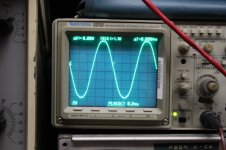
I have been slowly working on my 6hj5 build but I am in search of someone locally that has a scope so I can figure out the phasing of the antek transformer secondaries. The nice weather has put stop to all of my hobbies 🙂
Last edited:
BATs wired for 2500 ohm load (8 ohm load on the 4 ohm tap)...
I have been thinking about parallelling both channels to create a really big mono amp.
Or perhaps wire both sets of tubes into a single BAT at 1250 ohms...
Or perhaps wire both sets of tubes into a single BAT at 1250 ohms...
That's what I had in mind.
I am in search of someone locally that has a scope so I can figure out the phasing of the antek transformer secondaries.
Which Antek?
I have been slowly working on my 6hj5 build but I am in search of someone locally that has a scope so I can figure out the phasing of the antek transformer secondaries. The nice weather has put stop to all of my hobbies 🙂
You can call John and ask him --
You should be able to get a decent Heath, Knight or Eico scope at a hamfest for next to nothing up there in Minnesota.
I have been slowly working on my 6hj5 build but I am in search of someone locally that has a scope so I can figure out the phasing of the antek transformer secondaries. The nice weather has put stop to all of my hobbies 🙂
Just don't cut the leads before you've listening tested them. 😀
The jury is still out on the Antek AT-0358's (my Tannoy's need tweaking). That's for a different thread.
I should have followed up sooner to this. The Jury came back and the verdict was "horse apples". The folks at Antek were totally cool and took a return. I'm keeping the AT-1008's just because where the heck are you going to find 100w transformers for $60 a pop (when I got 'em). The latter should do better accprdomg to my limited testing.
So the Edcor's have arrive faster than expected, but I haven't had time to hook 'em up yet.
Last edited:
My power transformers an-4t360 and I have another one that I plan to use for the bias supply. I just wanted to make sure I had the 6volt heater secondaries in phase before I plugged the thing in. I was planning to parallel the pair of 6 volt windings. I made that mistake with my simple pp and blew a few fuses before I realized what mistake I had made. For the high voltage supply I just plan to connect the 360volt connections in series.Which Antek?
The only real issue I think I will run into with this amp is the amount of iron I have. Two toroidal transformers and two Edcor Output transformers.
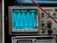
I finally got the 35LR6's stuffed into the red board and can now reach 250 watts at reasonable distortion levels and 300 watts at clipping. I ran some simple THD numbers with the following proceedure.
No GNFB used. A random pair of NOS (unmatched) tubes were installed. The tubes are biased at 32 mA each at idle. I set the signal generator to 20 Hz and cranked up the level to get 250 watts. I set the DC balance to equalize the currents in the output tubes. I set the AC balance for minimum distortion. These adjustments were not touched for the remainder of the test. Distortion at 5 power levels and 3 frequencies were recorded:
POWER 20 Hz 1KHz 20 KHz
1 W 1.06% .768% .884%
10 W 1.80% 1.61% 1.32%
100 W 2.43% 1.97% 1.99%
200 W 2.43% 2.06% 2.65%
250 W 4.68% 4.16% 4.40%
Or perhaps wire both sets of tubes into a single BAT at 1250 ohms... That's what I had in mind.
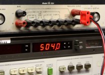
OK, I have pushed the red board and my luck far beyond my (and Petes) expectations. I wired both channels in parallel through a common OPT configured for 1250 ohms. It is now a single channel amp cranking out 504 watts at 5% distortion. No further measurements were made, and I think I will now quit while I am ahead (and still alive).
Sometimes you get the feeling that a really BIG BANG is about to happen, but you keep turning the knob upward. As I passed 525 watts there was this loud explosion. I have never smacked the kill button so quickly. After my nerves and the rest of my body stopped shaking, I realized that someone was lighting fireworks outside. Still, there is no way I'm turning this thing back on for a week or so.
I think that I will play with something small like a Simple P-P for the next few days. I haven't blown one of them up yet, and it would be far less likely to take down the power grid if it did blow up!
Attachments

Almost enough power to toast some English muffins. I think some joker back in the 80's actually wired up a Phase Linear 700 and ran a toaster with it for a laugh or two.
I think some joker back in the 80's actually wired up a Phase Linear 700 and ran a toaster with it for a laugh or two.
That sounds like something Bob Carver would do.
Speaking of toasty, I shut it down and waited for about 20 minutes before dissasebling the setup. The tubes were already cold but the load resistor was still pretty warm.
- Home
- Amplifiers
- Tubes / Valves
- Posted new P-P power amp design