Need to be careful regards the capacity of the cap used at the output of the rectifier. Too large results in excess RMS current. It is the RMS current that cooks transformers, not the average current.🙂
Adding a filament transformed to the DCPP
Well...
After a 4hr listening session at around i would guess 1-2 watt average output. The power transformer was HOT. I don't have a specific temperature but back of hand to side of the transformer was a max 3 one thousand count. (160F ish ?)
In short i pulled the trigger on a Hammond 167T6 filament transformer. I'll post the results... Fingers crossed, hopefully no smoke escapes in the process.
As a side note... I installed 2 x 40cmx40cm cpu heatsinks to the top of the PT.
Don't bother..little effect.
One of mine run hot enough that you don't touch it if you can avoid it - between 70 and 95 Celsius. I wouldn't worry if it doesn't smell.
ambient temperatures play a lot too, here in Manila at this time, ambient is easily 30*C, so you can just imagine how how any traffo can get...
Adding a filament transformed to the DCPP
Well...there is no burning smell at all....so you have a good point there.
Ambient temp was a nice 75deg central aired room, probably closer to 70 in winter months.
Filament transformer is on the way....so it's going in. This may not be the offending culprit.... But a 6 amp draw on a 6 amp supply seems suspect.
I understand and appreciate the PT choice. A huge Thank You is owed to Pete Millett for providing this accessible design and boards to the DIY crowd.
I once have tried feeding the filament externaly. The goal was to reduce the main transformer load and heating, but I don't think it made a large difference. Meanwhile I have ordered a Toroidy to replace the Edcor. My 2nd amp runs a Toroidy and its steel box temperature never exceed 50° C, and Tomasz@Toroidy told me it's fully ok and within specs. This is with a room temperature at ~ 20 °C. The Edcor in the same conditions reached 75°C, too much for my taste. My wall voltage is usually at 233-235V.
Until I get the Toroidy I might try using the amp with a filament feed to check if a dual-feed is a valid fix (and for my 3rd build, as I bought 3 PCBs from Pete Millett). A small SMPS could most probably fit in the case, but I have yet to find one I can adjust to 6.3V. There are buck converters but then you still need a 50Hz transformer, a diode bridge and capacitors. Not really a more compact approach and as MTBF goes not as reliable as direct cabling from a power transformer.
Until I get the Toroidy I might try using the amp with a filament feed to check if a dual-feed is a valid fix (and for my 3rd build, as I bought 3 PCBs from Pete Millett). A small SMPS could most probably fit in the case, but I have yet to find one I can adjust to 6.3V. There are buck converters but then you still need a 50Hz transformer, a diode bridge and capacitors. Not really a more compact approach and as MTBF goes not as reliable as direct cabling from a power transformer.
Adding a filament transformed to the DCPP
Hmmm.... Well fingers crossed that removing the filament load from the Edcor will help.
There is also the CCS bias circuit at play. The schematic shows 17ma per CCS device for a total of 34ma at 60v, maybe this is a factor...? The driver Tubes show 40ma each on schematic...so 194ma total on a 200ma rated HV
secondary. If I have my thinking straight, including the heater we see a total of around 280 watts at idle. I'm sure my method here is way too general to be accurate.
The filament Xfmr arrived today. I tightened it up and checked for mechanical noise and fit. All seems quiiet, although I tested it unloaded...again we'll see.
Will post back with results.
Adding a filament transformed to the DCPP
I was eager to see some results, so I wired in the filament transformer without mounting it .... Just to get at it quick. Everything went smoothly, no smoke, no hum or added noise.
So...
Same listening levels 1 to 2 watts average... Medium loud with 95db speakers.
Same room temperature....74dg f. ambient.
After 1 hr. Power transformer 98dg f. Filament transformer cool to touch.
After 2 hr. Power transformer 102dg f. Filament transformer barely warm.
After 4 hr. Power transformer 114dg f. Filament transformer 90dg f.
Success ? I would say yes...This certainly helped.
Does it now run cool after a 4hr medium loud listening session...No.
After 4hrs it was still hot, but not scary hot. Granted, I do not have specific readings from before the installation of the filament transformer.
The Best I can offer on this modification is that it takes the heat down a notch, but don't expect it to be pleasantly warm after an extended listening session. My official " GUESS " is a 50dg f. drop. Without temperature measurements from before the mod i can't be certain.
The next point of interest would be to find if the temperature levels off.
If any point of interest arises due to this mod... I'll post it.
Take Care All....
Hi!
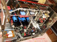
I show you when there is no compromise: 🙂
I know him well: he studied to be a Hungarian "amateur" railway mechanic.
This is how he builds an amplifier. Nothing heats up here except your wallet. 🙂 He hasn't made such an amp for himself, only for others, because he can't pay ...
Full silver wiring.
2 x 120VA transformer - own design
2 x 25VA transformer - own design
3 power supplies
(3 transformers) + output transformer
Monoblock!
E283CC - DC filament
Each electron tube has its own heating coil.
The picture also speaks.
The owner is in heaven when listening to music. 😉
Attachments
My 2 Cents
I've been running this as my main system amp for over 5 years now, my thoughts
- Yes its runs hot, at first i thought bit was due to running on 50Hz, no it just runs hot
- Has there been any degradation in sound, absolutely not!
- Is the Edcor undersized, absolutely.... will I change it.... no way 🙂
I've made a few of Pete's amps, always solid, always reliable.
Cheers
My 2 Cents
I've made a few of Pete's amps, always solid, always reliable.
Yes, I appreciate Pete's work, really a great contributor to our passion. By the way have someone heard from him recently ? No news on his web site since 14 months.
My 2 Cents
I've been running this as my main system amp for over 5 years now, my thoughts
- Yes its runs hot, at first i thought bit was due to running on 50Hz, no it just runs hot
- Has there been any degradation in sound, absolutely not!
- Is the Edcor undersized, absolutely.... will I change it.... no way 🙂
I've made a few of Pete's amps, always solid, always reliable.
Cheers
i design and build my own traffos to run 50hz....i have a couple of tube amps sent to down under...
Finally, after many years of waiting, disruptions and collecting parts... I was able to finally finish my amp! And it sounds good, but I am a bit worried about a few things...
The driver bias adjustment is very touchy. Is that normal? I measured a few things, and found that the bias pot measures as 5k in-circuit. So maybe I made a mistake there. In the end I did manage to get withing few mv of 400 though, and it seems stable enough, fluctuating a few mv up and down.
My next concern is the driver bias. The schematic shows 130V, but I have 210(Left)-220(Right). They are balanced without any problem though.
Overall the voltages seem to be a bit off, but I wonder how much is ok?
B+ says 340 +/-20, I have 365 (was 400 until I got bias adjusted)
C- is -65 instead of -60
The 325V are 355-360
-25-30 is -22-25
Should I start investigating or relax and enjoy the music?
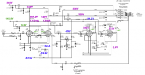
Attached are my voltages if that helps you relax. I could never get the driver stage plate voltages to what Pete measured. Somewhere in the thread someone suggests this is valve-dependent. Or R37 needs adjusting. But I get the same current as Pete...
Attachments


Attached are my voltages if that helps you relax. I could never get the driver stage plate voltages to what Pete measured. Somewhere in the thread someone suggests this is valve-dependent. Or R37 needs adjusting. But I get the same current as Pete...
That is very helpful, thank you! Will check some more and compare with your measurements. Looks like yours are a bit off in some places too. How did you measure milliamps? Disconnect, measure and then reconnect? Or is it all done by measuring voltages and calculating?
Great look Holtet, I like the top caps and blue cables !
To calculate the current, measure the voltage across the resistors and apply ohm's law. (I = U/R). Eg over R51 : (331 - 184) / 30k = 4.9 mA
By the way the dissipator look great but you will need to use a vacum cleaner from time to time or the management will complain 🙂
To calculate the current, measure the voltage across the resistors and apply ohm's law. (I = U/R). Eg over R51 : (331 - 184) / 30k = 4.9 mA
By the way the dissipator look great but you will need to use a vacum cleaner from time to time or the management will complain 🙂
Measuring voltages & calculating. So all approximate.How did you measure milliamps? Disconnect, measure and then reconnect? Or is it all done by measuring voltages and calculating?
I balance the driver stage using a USB scope's FFT for minimum THD% - which is very fiddly. And I bias the power stages using 2 multimeters - one on each test point for the channel, swapping back and forth as one channel alters the other's bias. I try and 'pre-match' the valves in to pairs using my uTracer. So this helps minimise adjustments between valves.
I balance the driver stage using a USB scope's FFT for minimum THD% - which is very fiddly.
I have tried this as well, but my Siglent Scope's FFT is too weak to help anything. So I have embarqued into the analysis chain : Jan Didden's Autoranger, a sound card (Steinberg UR-22) and REW... still soldering the autoranger so can't say if it will be better for this purpose. I guess so as the AD converter of this sound card is probably much better than the 8/10/wathever bits stuff in my cheap scope.
Great look Holtet, I like the top caps and blue cables !
To calculate the current, measure the voltage across the resistors and apply ohm's law. (I = U/R). Eg over R51 : (331 - 184) / 30k = 4.9 mA
By the way the dissipator look great but you will need to use a vacum cleaner from time to time or the management will complain 🙂
Thanks! The cables came from the cooking top of my parents' old kitchen that we were throwing out. They looked at me strangely when I said I needed those... It was too hard to explain that they would fit perfectly with my latest project 🙂
The dissipator is from an old intel cpu. I thought it looks quite cool. But obiously not optimal since it's designed to be used with a fan. And yeah, will be a PITA to clean after a while 🙂
- Home
- Amplifiers
- Tubes / Valves
- Posted new P-P power amp design