Measuring voltages & calculating. So all approximate.
I balance the driver stage using a USB scope's FFT for minimum THD% - which is very fiddly. And I bias the power stages using 2 multimeters - one on each test point for the channel, swapping back and forth as one channel alters the other's bias. I try and 'pre-match' the valves in to pairs using my uTracer. So this helps minimise adjustments between valves.
I see I will need some more equipment 😀
I do have an old HP distortion analyser I got last weekend. But I have no clue yet as to how it works, or if it even works...
Unfortunately because of the high voltages I get, I have to use the range with the least precision on my meters.
Thanks! The cables came from the cooking top of my parents' old kitchen that we were throwing out. They looked at me strangely when I said I needed those... It was too hard to explain that they would fit perfectly with my latest project 🙂
The dissipator is from an old intel cpu. I thought it looks quite cool. But obiously not optimal since it's designed to be used with a fan. And yeah, will be a PITA to clean after a while 🙂
Many of the old stoves used asbestos insulation for wires in hot places.🙂
Finally, after many years of waiting, disruptions and collecting parts... I was able to finally finish my amp! And it sounds good, but I am a bit worried about a few things...
The driver bias adjustment is very touchy. Is that normal? I measured a few things, and found that the bias pot measures as 5k in-circuit. So maybe I made a mistake there. In the end I did manage to get withing few mv of 400 though, and it seems stable enough, fluctuating a few mv up and down.
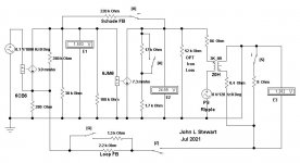
My next concern is the driver bias. The schematic shows 130V, but I have 210(Left)-220(Right). They are balanced without any problem though.
Overall the voltages seem to be a bit off, but I wonder how much is ok?
B+ says 340 +/-20, I have 365 (was 400 until I got bias adjusted)
C- is -65 instead of -60
The 325V are 355-360
-25-30 is -22-25
Should I start investigating or relax and enjoy the music?
that happens to me all the time...and that will not be your last...
Last edited:
Many of the old stoves used asbestos insulation for wires in hot places.🙂
Hmm. that's a good point. It was from the 90's though, so I think asbestos was mostly illegal by then. If not then any harm is already done. Better to just leave it there 🙂
And thanks for the uplifting words. It started to sound a bit worse after a while. Got me worried I had managed to kill the tubes aready. But it seems the driver balance had drifted quite far off (190 vs 240 volts on one channel). Adjusting it back made it sound much nicer again! I'm not so sure if the old Kef's are the best match, but I have a few pairs of speakers to try out now.
Just out of curiosity what is the damping factor of the DCPP? And does the primary impedance of the OPT affect this at all in any significant way?
Finally, after many years of waiting, disruptions and collecting parts... I was able to finally finish my amp! And it sounds good, but I am a bit worried about a few things...
The driver bias adjustment is very touchy. Is that normal? I measured a few things, and found that the bias pot measures as 5k in-circuit. So maybe I made a mistake there. In the end I did manage to get withing few mv of 400 though, and it seems stable enough, fluctuating a few mv up and down.
My next concern is the driver bias. The schematic shows 130V, but I have 210(Left)-220(Right). They are balanced without any problem though.
Overall the voltages seem to be a bit off, but I wonder how much is ok?
B+ says 340 +/-20, I have 365 (was 400 until I got bias adjusted)
C- is -65 instead of -60
The 325V are 355-360
-25-30 is -22-25
Should I start investigating or relax and enjoy the music?
Check R69 if not gone open. You need to desolder it to measure. Happened twice to me, replaced it with a 3W and now all ok. The symptom is too high B+ with 400mV ripple.
Just out of curiosity what is the damping factor of the DCPP?
On Pete Millett's website, his original build with 6dB global NFB loop measured about 2 ohms Zout, so with an 8 ohm speaker that should be damping factor of about 4.
And does the primary impedance of the OPT affect this at all in any significant way?
Yes.
--
Thanks rongon. I could see the Zout but no conversion chart to damping factor. That helps a lot.
What impact does Total primary Inductance have on damping? Toroid output transformers have massive amounts from Lp = 466 [H] to Lp = 1500[H] based on the 8K models I am looking at. Would this simply lower bass distortion or add to damping as well?
What impact does Total primary Inductance have on damping? Toroid output transformers have massive amounts from Lp = 466 [H] to Lp = 1500[H] based on the 8K models I am looking at. Would this simply lower bass distortion or add to damping as well?
I'm probably not the guy to ask about that. Since I'm not an engineer, I'm not as well educated on this stuff as others here.
From what I understand, the primary inductance Lpri defines how low in frequency the transformer can pass signal from primary to secondary. The easiest way to increase Lpri is to wind more copper around the core, but that increases the DC resistance (DCR) of the winding. A higher primary DCR will change damping, I believe for the worse. Usually increased Lpri comes at the cost of increased interwinding capacitance, which causes a lower limit to the high frequency response as well as possible peaking/ringing at higher frequency. I understand that this is why smaller, lower power OPTs generally 'sound better' than larger, high power OPTs.
Toroid push-pull output transformers would be great except that their performance degrades quickly with current draw imbalance between the driving tubes. Usually amp designs that use toroidal OPTs have provisions for adjusting the plate current of the output tubes individually. EI-core OPTs are more tolerant of plate current imbalance, even though their performance is not as good as toroids under ideal conditions. Since conditions are hardly ever ideal, an EI-core OPT may actually perform better in real life.
Everything is a compromise between this and that.
However, I'm just a hack. Perhaps someone with deeper knowledge will be willing to drop in and set us straight.
--
Last edited:
the quality of the core material used has a huge impact..
chapter 5 of RDH4 will give you many insights....
Patrick Turner has a webpage detailing audio transformer designs...
chapter 5 of RDH4 will give you many insights....
Patrick Turner has a webpage detailing audio transformer designs...
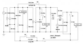
This amp uses plate to grid feedback (output plate to driver plate here) in the output stage. That reduces the output impedance (Rp of the pentode) of the output tube into a triode like region making simple calculations more difficult.
The driver tube even plays a role here since it's Rp affects the feedback ratio.
To further complicate things GNFB can also be used for two negative feedback paths in the complete amp. Both have a large influence on the output impedance / damping factor.
I spent some considerable time with three of these amplifiers and wound up changing the driver to a 6GU5 hexode and adjusting the feedback and driver tube plate load resistors to get the best sound quality without GNFB.
Pete followed my 6GU5 choice in his latter iterations of this amp. It gas one of the highest Gm's of the pin compatible 7 pin tubes.
If a single ended amp uses a Pentode and no negative feedback, and the output transformer has a lot of leakage reactance from primary to secondary, then . . .
The high impedance pentode rp, sees a rising load impedance as leakage reactance becomes significant.
So . . . the pentode plate voltage gain increases as the leakage reactance increases.
That helps to flatten out the high frequency roll off that the leakage reactance to the secondary caused in the first place.
Did you ever see a no-feedback pentode have a cap, or a cap and series resistor across the output transformer primary (or similarly from the pentode plate to ground).
If you have not seen it, then . . .
Check out some 30s, 40s, and 50s radio schematics, and you will see that.
No, I am not talking about the ones that use a rheostat instead of a fixed resistor.
The one with a rheostat is a variable high frequency control.
Just saying.
jhstewart9,
Thanks for that write-up.
I really liked the easy to see results at the low end, triode vs pentode.
And . . .
It also made me remember the old radios, and the compensation network for the no-feedback pentodes.
Thanks for that write-up.
I really liked the easy to see results at the low end, triode vs pentode.
And . . .
It also made me remember the old radios, and the compensation network for the no-feedback pentodes.
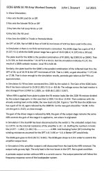
Opus ll- 6CB6 6JM6 SE FB Amp Worked Example
These sim's uses symbols for the tubes that some newbies may not be familiar with. In short, each tube is represented by a voltage controlled current source, ie mA per Volt in parallel with a resistor of R Ohms which is simply rp. The Voltage controlled current source also uses units of conductance, the mho. In this case it is mmho or milli mho which is simply mA/V, the transconductance of tte tube. Conductance G is simply 1/R.
The advantage of this kind of solution is that it gives a good estimate of circuit performance without the complication of all the DC voltages involved. And used extensively in all the textbooks covering electronic engineering.🙂
The circuit constants used are similar to those in Pete Millet's amplifier in this thread.🙂
Attachments


So, after half a year it works a charm, but continues burning the mosfet in the b+ line. Already equipped a 900V one, from time to time it gets shot, and can't understand why?
FQPF8N90C yes it doesDoes your MOSFET contain built-in protection diodes? If not, you may need to add some.
- Home
- Amplifiers
- Tubes / Valves
- Posted new P-P power amp design